
Related Manuals for bester SPF 405-SA


Summary of Contents for bester SPF 405-SA
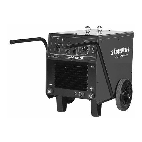
- Page 1 I-207-529-1 11/2005 Rev. 0 SPF 405-SA OPERATOR’S MANUAL INSTRUKCJA OBSŁUGI LINCOLN ELECTRIC BESTER S.A. ul. Jana III Sobieskiego 19A, 58-260 Bielawa, Poland www.bester.com.pl...
- Page 2 że zostało zaprojektowane zgodnie z wymaganiami następujących norm: EN 60974-1, EN 60974-10 Tomasz Domagalski Operations Director LINCOLN ELECTRIC BESTER S.A., ul. Jana III Sobieskiego 19A, 58-260 Bielawa, Poland 11/04...
- Page 3 02/05 THANKS! For having choosen the QUALITY of the Lincoln Electric products. • Please Examine Package and Equipment for Damage. Claims for material damaged in shipment must be notified immediately to the dealer. • For future reference record in the table below your equipment identification information. Model Name, Code & Serial Number can be found on the machine rating plate.
-
Page 4: Table Of Contents
ENGLISH INDEX Safety ...................................A-1 Installation and Operator Instructions........................... A-2 Electromagnetic Compatibility (EMC) ........................... A-4 Technical Specifications ...............................A-4 SKOROWIDZ POLSKI Bezpieczeństwo Użytkowania ............................C-1 Instrukcja Instalacji i Eksploatacji ..........................C-2 Kompatybilność Elektromagnetyczna (EMC) .......................C-4 Dane Techniczne .................................C-5 Spare Parts, Wykaz Części Zamiennych ........................1 Electrical Schematic, Schemat Elektryczny........................ -
Page 5: Safety
Safety 11/04 WARNING This equipment must be used by qualified personnel. Be sure that all installation, operation, maintenance and repair procedures are performed only by qualified person. Read and understand this manual before operating this equipment. Failure to follow the instructions in this manual could cause serious personal injury, loss of life, or damage to this equipment. -
Page 6: Installation And Operator Instructions
Installation and Operator Instructions Read this entire section before installation or operation of the machine. Check the input voltage, phase, and frequency supplied to this machine before turning it on. Verify the connection of grounding wires from the machine to the Location and Environment input source. - Page 7 machine has been exceeded. Leave the machine 12. Fuse: This fuse protects the Fan Circuit. on to allow the internal components to cool, when the lamp turns off normal operation is possible. 13. Power Input Socket: Connect the supply plug to the existing input cable, that is rated for the machine as •...
-
Page 8: Electromagnetic Compatibility (Emc
Electromagnetic Compatibility (EMC) 11/04 This machine has been designed in accordance with all relevant directives and standards. However, it may still generate electromagnetic disturbances that can affect other systems like telecommunications (telephone, radio, and television) or other safety systems. These disturbances can cause safety problems in the affected systems. Read and understand this section to eliminate or reduce the amount of electromagnetic disturbance generated by this machine. -
Page 9: Bezpieczeństwo Użytkowania
Bezpieczeństwo Użytkowania 11/04 OSTRZEŻENIE Urządzenie to może być używane tylko przez wykwalifikowany personel. Należy być pewnym, że instalacja, obsługa, przeglądy i naprawy są przeprowadzane tylko przez osoby wykwalifikowane. Instalacji i eksploatacji tego urządzenia można dokonać tylko po dokładnym zapoznaniu się z tą instrukcją obsługi. Nieprzestrzeganie zaleceń zawartych w tej instrukcji może narazić... -
Page 10: Instrukcja Instalacji I Eksploatacji
ZNAK BEZPIECZEŃSTWA: Urządzenie to jest przystosowane do zasilania sieciowego, do prac spa- walniczych prowadzonych w środowisku o podwyższonym ryzyku porażenia elektrycznego. Instrukcja Instalacji i Eksploatacji Przed instalacją i rozpoczęciem użytkowania tego urządzenia należy przeczytać cały ten rozdział. Warunki Eksploatacji minuty lub zmniejszyć... - Page 11 urządzeniem może współpracować jednostka zdalnego sterowania K10095-1-15M lub K870. Ten Elementy regulacyjne i właściwości przełącznik przekazuje sterowanie prądem wyjściowym z pokrętła regulacji (punkt 7) na zdalne sterowanie i odwrotnie. Regulator Arc Force: Jest to funkcja stosowana w metodzie spawania MMA, która polega na chwilowym wzroście prądu wyjściowego dla przerwania zwarcia pomiędzy elektrodą...
-
Page 12: Kompatybilność Elektromagnetyczna (Emc
• • Przy pomocy pokrętła prądu wyjściowego ustawić Sprawdzać stan i działanie wentylatora wymaganą wartość prądu spawania. chłodzącego. Utrzymywać czyste otwory wlotu i • wylotu powietrza chłodzącego. Zachowując właściwe zasady można przystąpić do spawania. Konserwacja okresowa (po każdych 200 Konserwacja godzinach pracy, lecz nie rzadziej niż... -
Page 13: Dane Techniczne
Dane Techniczne PARAMETRY WEJŚCIOWE Napięcie zasilania Pobór mocy z sieci Częstotliwość 230 / 400V ± 10% 34 kVA @ 35% cykl pracy 50 Hertz (Hz) 3 - fazy ZNAMIONOWE PARAMETRY WYJŚCIOWE PRZY 40°C Cykl pracy Prąd wyjściowy Napięcie wyjściowe (Oparty na 10 min. okresie) 400A 36.0 Vdc 315A... -
Page 14: Spare Parts, Wykaz Części Zamiennych
Użyj tylko częci z oznaczeniem “X” w kolumnie pod numerem głównym przywołującym stronę (assembly page) z indeksem modelu (# znajdź zmiany na rysunku). SP1100 Rev. 0 07/03 SPF 405 ASSEMBLY PAGE NAME CODE B NO.: FIGURE NO.: NO.: 1100 B18326-1 SPF 405-SA Figure A... - Page 15 Figure A: Machine Assembly Item Description Part Number TRANSFORMER T1 B-4247-453-2R CHOKE L1 C-4244-373-2R RECTIFIER SET V 1156-112-145R FAN M1 1111-311-084R CONTROL CIRCUIT BOARD USM-12 C-3731-398-1R DIGITAL AMMETER WA/H-400 C-3731-386-1R MAIN SWITCH K1 1115-260-113R LAMP H1 0917-421-002R LAMP H2 0917-421-024R SWITCH K2 1158-650-023R SOCKET X3...
-
Page 16: Electrical Schematic, Schemat Elektryczny
Electrical Schematic, Schemat Elektryczny... -
Page 17: Accessories, Akcesoria
Accessories, Akcesoria K14007-1 Welding Cable with the Holder for Coated Electrodes 5m. Kabel spawalniczy z uchwytem elektrody 5m K14008-1 Ground Cable with the Work Clamp 5m. Kabel spawalniczy z zaciskiem uziemiającym 5m. K10095-1-15M Hand Amptrol. Ręczny regulator prądu. K870 Foot Amptrol. Nożny regulator prądu.
Need help?
Do you have a question about the SPF 405-SA and is the answer not in the manual?
Questions and answers