
Related Manuals for Sam4s ELLIX 35III


Summary of Contents for Sam4s ELLIX 35III
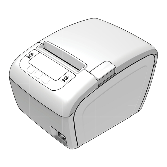
- Page 1 OPERA ATOR’S S Manu All s specificati ons are su ubject to c change wit thout notic ce...
- Page 2 Warning - U.S. This equipment has been tested and founded to comply with the limits for a Class A digital device pursuant to Part 15 of the FCC Rules. These limits are designed to provide reasonable protection against harmful interference when the equipment is operated in a commercial environment.
- Page 3 Caution Some semiconductor devices are easily damaged by static electricity. You should turn the printer “OFF”, before you connect or remove the cables on the rear side, in order to guard the printer against the static electricity. If the printer is damaged by the static electricity, you should turn the printer “OFF”...
- Page 4 LEGISLATION AND WEEE SYMBOL 2002/96/CE Waste Electrical and Electronic Equipment Directive on the treatment, collection, recycling and disposal of electric and electronic devices and their components. The crossed dustbin symbol on the device means that it should not be disposed of with other household wastes at the end of its working life.
-
Page 5: Table Of Contents
Table of Contents CHAPTER 1. SETTING UP THE PRINTER ........2 1-1. U ................2 NPACKING 1-2. C ............... 2 ONNECTING THE ABLES 1-3. C ............3 ONNECTING THE OST DEVICE 1-4. C ............. 3 ONNECTING THE RAWER 1-5. C ............. -
Page 6: Chapter 1. Setting Up The Printer
hapter 1. Sett tting U p the P Printer 1. Unpac king Your p printer box shou uld include thes se items. If any items are dama aged or missing, , please conta ct your dealer f for assistance. 2. Conne cting the e Cables You c... -
Page 7: Connecting The Host Device
3. Conne cting the e Host de evice You n need the approp priate interface c cable. 1. Pl lug the cable co onnector secure ly into the print ter’s interface co onnector. 2. Ti ighten the screw ws on both side es of the cable c connector. -
Page 8: Connecting The Drawer
5. Conne cting the e Power Supply Use th he optional Pow wer supply for yo our printer. If the power supply’s s rated voltage a and your outlet’ ’s voltage do no ot match, contac ct your dealer r for assistance. . -
Page 9: Installing Options & Replacing The Paper Roll
1-6 6. Installing Optio ons & Replacing t t he Pape er Roll - 5 -... -
Page 10: Partition Installation
1-6- -1. Partitio n Installati You c can install the pa artition for 58m m paper printin ng on ELLIX35II Push the Open- Button and ope en the Cover-Op pen. Insert the Partit tion into the Pap per-Supply as sh hown. - Page 11 ------- -------------------- ------------------- -------------------- ------------------- - ------------------- ------ (Cut it for the e fix wall mount t bracket) #. W Wall mounting g hole data - 7 -...
-
Page 12: Splash Cover Installation
1-6- -3. Splash Cover Inst tallation 1-6- -4. Paper R Roll Installa ation 1. O Open the paper r roll cover by pre essing the cover r -open button. - 8 -... - Page 13 2. Re emove the used d paper roll core e if there is one 3. In nsert the paper roll as shown. 4. Pu ull out a small a amount of paper r, as shown. Th hen close the cover. Tear off the e paper s shown - 9 -...
-
Page 14: Adjustments And Settings
7. Adjust ments an nd Settin The E ELLIX35III is set t up at the facto ory to be approp priate for most users. It does, h however, offer s some settings fo or users with sp pecial requireme ents. The E ELLIX35III has D DIP switches tha... -
Page 15: Serial Interface(Rs-232C) Dip Switch Set
1-7-1. Serial Interface(RS-232C) DIP Switch Set ■ DIP Switch Set 1 Functions ◆ Baud rate selection ■ Dip Switch Set 2 Functions * Kitchen Bell is option. ◆ Print Density - 11 -... -
Page 16: Parallel Interface Dip Switch Set
1-7-2. Parallel Interface DIP Switch Set ■ Dip Switch Set 1 Functions ■ Dip Switch Set 2 Functions * Kitchen Bell is option. ◆ Print Density - 12 -... -
Page 17: Serial-Ethernet Interface Dip Switch Set
1-7-3. Serial-Ethernet Interface DIP Switch Set ■ DIP Switch Set 1 Functions ◆ Baud rate selection ■ Dip Switch Set 2 Functions * Kitchen Bell is option. ◆ Print Density - 13 -... -
Page 18: Device Settings By App
1-7- -4. Device Settings b by APP ■ A APP Installa ation ◆ Installation Method 1 – – Easy Install ation Mode ◆ 1. Configure N NFC Function n from User’s s smartphon e into Read/ /Write, P2P Mode. . (not workab ble in a Card d Mode) 2. - Page 19 ■ Device Settings 1. In Device Settings Menu, Run a Config the setting values. 2. Change setting values you wish to change on a Setting screen. After completion of setting, touch the upper screen. 3. If the message “Tag on ELLIX30III” appears in the middle of screen, then tag a smartphone on Printer.
-
Page 20: Using The Printer
8. Using t the Print You c can control the b basic paper feed ding operations of the printer w with the button o on the contro ol panel. The ind dicator lights he elp you monitor the printer’s st atus. -
Page 21: Chapter 2. Appendix
hapter 2. APP PENDIX 1. Adjust ting the Paper N ear-End Sensor Locati The s ensor has five s sensitivity settin ngs. The factory y default setting is at position # Push the open b button and open n the printer cov ver. -
Page 22: Rinter Head Cleaning
2. Printe er Head C Cleaning Paper r dust on the he eating elements may lower the printing quality . In this case, c clean the printe er head as follow 1) Pow wer off the prin ter. 2) Op pen the printer c cover. -
Page 23: Rror Status And Error Resolution
3. Error Status a nd Error r Resolut tion The p printer buzzer so ounds momenta rily or continuou usly and the ER ROR LED blinks s when the printe er indicates an E Error status. Error Status Indicato rs include: Cutter Jam m ( Buzzer an nd ERROR LE... - Page 24 Cutter Not Home ( Buzzer and ERROR LED status ) If the cutter blade is not in home position when the normal waiting time, the printer enters Cutter Not Home error status. The buzzer and ERROR LED beeps and blinks as like: (Beep beep beep----, Beep beep beep----, Beep beep beep----) Cutter Not Home If you want to clear error status above, open and close printer cover 2~3 times.
-
Page 25: General Printer Specification
2-4. Specification 2-4-1. General Printer specification 2-4-2 Paper specification *The Following paper can be used instead of the specified paper above. TF50KS-E : Nippon Paper industries Co., Ltd. PD 160R : New Oji Paper Mfg, Co.,Ltd. F380 : Kansaki Specialty Papers,Inc.(USA) *Mitsubishi PB670 / PB770 are two color mode papers - 21 -... - Page 26 Rev 1.0 JK68-61079B...
Need help?
Do you have a question about the ELLIX 35III and is the answer not in the manual?
Questions and answers