
Subscribe to Our Youtube Channel
Related Manuals for Haulotte Group STAR 6 P


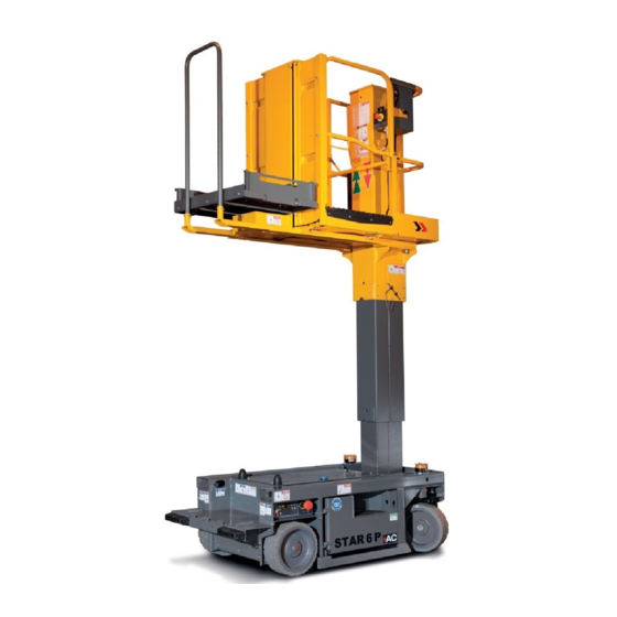
Summary of Contents for Haulotte Group STAR 6 P
- Page 1 Maintenance Book Maintenance Book STAR 6 P - STAR 13 P 4000562980 E 07.16 USA / GB...
- Page 2 STAR 6 P - STAR 13 P 4000562980 E 07.16 USA / GB...
-
Page 3: Table Of Contents
Maintenance Book CONTENTS Preface - Foreword 1 - Symbols and colors ..... . Safety 1 - General safety rules ..... 1.1 - Maintenance implementation. - Page 4 Maintenance Book Familiarization 1 - Primary machine components ... . 1.1 - Layout............1.2 - Maintenance support .
- Page 5 Maintenance Book Inspection and maintenance schedule 1 - Maintenance Schedule ....2 - Inspection program ..... 3 - Daily inspection .
- Page 6 Maintenance Book Trouble shooting and diagram 1 - Trouble shooting ..... . 1.1 - Recommendations......... . . 1.2 - Description .
-
Page 7: Preface - Foreword
STAR 6 P - STAR 13 P - Preface - Foreword Preface - Foreword You have just purchased a HAULOTTE® product and we would like to thank you for your business. The Aerial Work Platform is a mechanical device primarily designed and manufactured with the intent to position people with the necessary tools and material to overhead elevated temporary workplaces. -
Page 8: Symbols And Colors
STAR 6 P - STAR 13 P - Preface - Foreword 1 - Symbols and colors Symbols and colors are used to alert the operator of safety precautions and/or to highlight important safety information. The following safety symbols are used throughout this manual to indicate specific hazards and the hazard severity level when operating or maintaining the Aerial Work Platform. - Page 9 STAR 6 P - STAR 13 P - Preface - Foreword D e c a l s Color Title Description Danger : Indicates a hazardous situation which if not avoided, WILL result in death or serious injury. Warning : Indicates a hazardous situation which if not avoided, COULD result in death or serious injury.
- Page 10 STAR 6 P - STAR 13 P - Preface - Foreword Notes 4000562980 E 07.16 USA / GB...
-
Page 11: Safety
STAR 6 P - STAR 13 P - Safety Safety 1 - General safety rules 1.1 - MAINTENANCE IMPLEMENTATION Your safety and the safety of the people around are essential. Make sure the work area is clean in order to not to pollute the system of the machine. -
Page 12: Uncontrolled Movement Hazard
STAR 6 P - STAR 13 P - Safety Never leave the hydraulic cylinders fully extended before switching off the machine, or when stationary for an extended period of time. Keep the elements of the machine in configuration of maintenance thanks to mechanics devices. -
Page 13: Electrocution Hazards
STAR 6 P - STAR 13 P - Safety 1.3 - ELECTROCUTION HAZARDS The machine is not electrically insulated and does not provide protection from contact or proximity to electrically charged conductors. Always position the lift at a safe distance from electrically charged conductors to ensure that no part of the machine is within an unsafe area. -
Page 14: Explosion / Fire Hazards
STAR 6 P - STAR 13 P - Safety 1.4 - EXPLOSION / FIRE HAZARDS Always wear protective clothing and eye wear when working with batteries and power sources/systems. N.B.-:-A CID IS NEUTRALIZED WITH SODIUM BICARBONATE AND WATER • Do not start the engine if you smell or detect liquid propane gas (LPG), gasoline, diesel fuel or other explosive substances. -
Page 15: Maintenance And Repair Training
Only authorized and qualified operators may operate HAULOTTE® machines. 2.3 - HAULOTTE SERVICES® The HAULOTTE Group is at your service in all 5 continents of the world via an extensive network of its own factory trained technicians, who are ready to respond to your every need. -
Page 16: Product Modification
Any modification may violate Haulotte design parameters, government regulations and industry standards. If you desire a modification to the product, submit a request in writing to HAULOTTE Group. With the utmost care to ensure enhanced reliability and greater safety of the HAULOTTE® products, it is pertinent that when a "Service or Safety Bulletin"... -
Page 17: Manufacturer's Warranty
STAR 6 P - STAR 13 P - Safety 3 - Manufacturer's warranty 3.1 - WARRANTY ACCEPTANCE On reception of his machine, the owner or rental company must check the machine's condition and fill out the machine reception slip provided. -
Page 18: Warranty Conditions
STAR 6 P - STAR 13 P - Safety If no particular agreement has been made, any claims made after the previously established warranty period has expired will be refused. The present warranty does not cover damage that may result directly or indirectly from any flaws or defects covered by the latter : •... - Page 19 STAR 6 P - STAR 13 P - Familiarization Familiarization Notes 4000562980 E 07.16 USA / GB...
-
Page 20: Primary Machine Components
STAR 6 P - STAR 13 P - Familiarization 1 - Primary machine components 1.1 - LAYOUT S T A R S T A R 4000562980 E 07.16 USA / GB... - Page 21 STAR 6 P - STAR 13 P - Familiarization Marking Description Marking Description Chassis Guardrail Platform Platform access step (on both sides) Platform control box Battery bay (block) Tie-down (and/or forklift loading) C136 Front steer wheels Ground control box C142...
-
Page 22: Maintenance Support
STAR 6 P - STAR 13 P - Familiarization 1.2 - MAINTENANCE SUPPORT The maintenance stand must be in place before any maintenance operation is begun. Placing the machine in maintenance configuration : • Raise the telescoping mast upto 1,20 m (3 ft 11in). -
Page 23: Picking Tray
STAR 6 P - STAR 13 P - Familiarization 1.3 - PICKING TRAY 1.3.1 - Description This picking tray is designed as an attachment to the platform to transport parcels to and from elevated heights. 1.3.2 - Safety precautions Before using machine in the picking mode : •... -
Page 24: Special Decal
STAR 6 P - STAR 13 P - Familiarization 1.3.5 - Special decal The load on the picking tray should not exceed 80 kg(176 lb). 1.3.6 - Operation refer to Section B 3.6 Auxiliary control box to perform the picking tray and mast movements. -
Page 25: Ground Control Box
STAR 6 P - STAR 13 P - Familiarization 1.4 - GROUND CONTROL BOX 1.4.1 - Layout G e n e r a l v i e w C o n t r o l s a n d i n d i c a t o r s... -
Page 26: Haulotte Activ'screen
STAR 6 P - STAR 13 P - Familiarization 1.4.2 - HAULOTTE Activ'Screen Upon starting and during operation of the machine, the LCD screen "Activ'Screen" located on the ground control box displays in real time the machine operating status. H A U L O T T E... - Page 27 STAR 6 P - STAR 13 P - Familiarization LCD screen At startup At startup with the ground or platform controls selected; system initiates a self check : • Bar gets filled up. • Home screen comes on with status icon of the machine - okay to proceed functioning the controls.
- Page 28 STAR 6 P - STAR 13 P - Familiarization • Pressing either one of the buttons , the following screen shot will be displayed : Symbol Description Software part number Software version + Screen software version + Screen version Screen identification + Screen software version Machine serial number displayed •...
- Page 29 STAR 6 P - STAR 13 P - Familiarization Alarm status Alarm status displayed as applicable - samples shown below • Tilt • Low battery 4000562980 E 07.16 USA / GB...
- Page 30 STAR 6 P - STAR 13 P - Familiarization • Present fault • Platform control box E-stop button pressed in (de-energized) 4000562980 E 07.16 USA / GB...
-
Page 31: Platform Control Box
STAR 6 P - STAR 13 P - Familiarization 1.5 - PLATFORM CONTROL BOX 1.5.1 - Layout G e n e r a l v i e w 100% 4000311500c 4000562980 E 07.16 USA / GB... - Page 32 STAR 6 P - STAR 13 P - Familiarization C o n t r o l s a n d i n d i c a t o r s Marking Description Function Tilt indicator Machine on excessive slope Overload indicator...
-
Page 33: Auxiliary Control Box
STAR 6 P - STAR 13 P - Familiarization 1.6 - AUXILIARY CONTROL BOX 1.6.1 - Layout G e n e r a l v i e w C o n t r o l s a n d i n d i c a t o r s... -
Page 34: List Of Actuators And Sensors
STAR 6 P - STAR 13 P - Familiarization 2 - List of actuators and sensors 2.1 - SENSORS AND ACTUATORS S e n s o r s a n d a c t u a t o r s 4000562980 E 07.16... -
Page 35: Consumables
STAR 6 P - STAR 13 P - Familiarization Description Name Pothole limit sensor SQ144 Pothole limit sensor SQ145 Position sensor mast folded SQ721 Door sensor - Door 1 - Right SQ700 Door sensor - Door 2 - Left SQ701... -
Page 36: Ingredient
STAR 6 P - STAR 13 P - Familiarization 4 - Ingredient Ingredient HAULOTTE® code Hydraulic oil 2420801310 Hydraulic oil (Winter option) 2505002640 Biological hydraulic oil 2820304310 4.1 - HYDRAULIC OIL Hydraulic oils must comply with the following requirements : •... -
Page 37: Lubrication Diagram
STAR 6 P - STAR 13 P - Familiarization 5 - Lubrication diagram L i s t i n g r e d i e n t s Marking Ingredient Symbol HAULOTTE® code Hydraulic oil (Standard) - Barrel 209 l(55,2 gal US) -
Page 38: Greasing Points Localization
STAR 6 P - STAR 13 P - Familiarization 5.1 - GREASING POINTS LOCALIZATION • Wheel steering pivots : 2 on the chassis. Lubricate the pivots with lead-free grease. • Mast lubrication : 6 - Machine specifications 6.1 - MOVEMENT SPEED To allow checking operation, refer to the following table about originally time per movement. -
Page 39: Maintenance Schedule
STAR 6 P - STAR 13 P - Inspection and maintenance schedule Inspection and maintenance schedule 1 - Maintenance Schedule There are a number of factors which can affect the design life including but not limited to, severity of operating conditions/routine maintenance. - Page 40 STAR 6 P - STAR 13 P - Inspection and maintenance schedule Intervals Area After 1500 h After 5000 h After 125 h After 250 h Daily (hours) or (hours) or (hours) or 1 year (hours) or 1 year 3 years...
- Page 41 STAR 6 P - STAR 13 P - Inspection and maintenance schedule Intervals After 1500 h After 5000 h Area After 125 h After 250 h Daily (hours) or (hours) or (hours) or 1 year (hours) or 1 year 3 years...
- Page 42 STAR 6 P - STAR 13 P - Inspection and maintenance schedule Intervals After 1500 h After 5000 h Area After 125 h After 250 h Daily (hours) or (hours) or (hours) or 1 year (hours) or 1 year 3 years...
-
Page 43: Inspection Program
STAR 6 P - STAR 13 P - Inspection and maintenance schedule 2 - Inspection program The machine must be inspected on a regular basis at intervals in accordance with the requirements set forth in the Country of use but no less than once a year. The purpose of the inspection is to detect any defect which could lead to an accident during routine use of the machine. -
Page 44: Daily Inspection
STAR 6 P - STAR 13 P - Inspection and maintenance schedule 3 - Daily inspection The content and method of inspection must be conducted by operators before using the machine, it includes a visual inspection and functional and security systems testing of the machine. - Page 45 STAR 6 P - STAR 13 P - Inspection and maintenance schedule Daily inspection Visual inspection without disassembly Check level To check by test Corrected applicable Manuals and displays. Clean or replace if necessary. Presence, cleanliness and legibility of the...
- Page 46 STAR 6 P - STAR 13 P - Inspection and maintenance schedule Extending structure (jib, mast) No cracks, broken weld, paint chipped No deterioration and visible damage No screws missing / loose parts No foreign material / impurities in joints or slides...
- Page 47 STAR 6 P - STAR 13 P - Inspection and maintenance schedule Battery electrolyte level Level of centralized battery refilling No screws missing / loose parts Presence and good condition of hydraulic hose Presence and good condition of engine components Presence and good condition of the batteries: terminations and clamps, electrolyte level ...
-
Page 48: Periodic Inspection
STAR 6 P - STAR 13 P - Inspection and maintenance schedule 4 - Periodic inspection The Periodic inspection is a thorough inspection of the operation and safety features of the machine. This inspection must be done before the sale/resale of the machine and at a frequency of 125 hours or once a year, according to the regulations. - Page 49 STAR 6 P - STAR 13 P - Inspection and maintenance schedule Periodic inspection In addition to the daily inspection program Area Type of intervention Area Type of intervention Chassis assembly Functions and controls Platform control box (indicators, Wheel nuts and bolts etc.)
-
Page 50: Reinforced Inspection
STAR 6 P - STAR 13 P - Inspection and maintenance schedule 5 - Reinforced inspection Reinforced periodic inspection is a thorough inspection of the machine structure and to ensure proper functionality. It must be performed every 1500 h or every 3 years, whichever occurs first. - Page 51 STAR 6 P - STAR 13 P - Inspection and maintenance schedule Reinforced inspection In addition to daily and periodic inspections Area Type of intervention Area Type of intervention Chassis assembly Functions and controls Platform control box (indicators, Wheel nuts and bolts etc.)
-
Page 52: Major Inspection
STAR 6 P - STAR 13 P - Inspection and maintenance schedule 6 - Major inspection Major inspection is to ensure the continued safe use of the aerial work platform past the designed life of the machine and for predicted use until the next recommended major inspection. It must be performed every 5000 h or every 5 years, whichever occurs first, and subsequently every 5 years thereafter. - Page 53 STAR 6 P - STAR 13 P - Inspection and maintenance schedule Major inspection In addition with daily, periodic, and reinforced inspections Area Type of intervention Area Type of intervention Chassis assembly Functions and controls Platform control box (indicators, Wheel nuts and bolts etc.)
- Page 54 STAR 6 P - STAR 13 P - Inspection and maintenance schedule N.B.-:-T HAULOTTE HE LIST OF AINTENANCE NSPECTION HEETS IS NOT EXHAUSTIVE ONTACT ® ERVICES FOR ADDITIONAL OTHER SHEETS 4000562980 E 07.16 USA / GB...
-
Page 55: Structural Part Inspection
General data Structural part inspection MS0001 General data Structural part inspection 1 - You will need • Standard tool kit • Protective goggles • Place barriers around the perimeter of the work area • Gloves Exclusively use tools and auxiliary average adapted. Always wear necessary safety clothing. For safety reasons, imperatively respect the following stages during the tests : •... - Page 56 General data Structural part inspection MS0001 3 - Control and maintenance To guarantee the integrity of the machine, it is necessary to carry out periodical controls on the mechanical structure such as defines hereafter. 3.1 - DAILY INSPECTION All the accessible structural part without disassembling must be subjected to a fast visual inspection.
- Page 57 General data Structural part inspection MS0001 3.2 - MAJOR INSPECTION A thorough inspection of the structural parts must be realized all the 5000 h or 10 years with disassembling of the element to check the entirety of the welding. All structural part listed Section Familiarization must be disassembled and all weldsmust be review using non-destructive checks.
- Page 58 General data Structural part inspection MS0001 3.3 - FUNCTIONAL TESTS The following tests must be carried out each 250 h or 6 months or afterwards : • An important technical intervention. • An accident resulting from a failure of a major component. The following tests must be realized by a qualified staff under secure conditions.
-
Page 59: Pins And Bearing Inspection
General data Pins and bearing inspection MS0002 General data Pins and bearing inspection 1 - You will need • Standard tool kit • Protective goggles • Place barriers around the perimeter of the work area • Gloves Exclusively use tools and auxiliary average adapted. Always wear necessary safety clothing. 2 - Preliminary operation The operations of disassembling if they exist should be carried out only on the installations completely disconnected and must be entrusted only to people having the necessary technical training. - Page 60 General data Pins and bearing inspection MS0002 3 - Control and maintenance The control of pins, stop pins, bushes and bearing must be carried out according to the following recommendations : • Every day before use : Fast visual inspection without disassembling. •...
- Page 61 General data Pins and bearing inspection MS0002 5 - Procedure of reassembly 5.1 - PINS AND BUSHES For OPTIMUM 8 - OPTIMUM 1931 E only : Never grease the pins and rings of scissor arms. When reassembling bearings and pins ensure that : •...
- Page 62 General data Pins and bearing inspection MS0002 5.2 - BEARINGS For the reassembly of bearings, respect the following stages : • Clean boring and/or the pins to remove all the foreign bodies. • Slightly lubricate boring and/or pins. • Lubricate the ring of the bearing slightly. •...
-
Page 63: Cylinder Inspection
General data Cylinder inspection MS0003 General data Cylinder inspection 1 - You will need • Standard tool kit • Protective goggles • Place barriers around the perimeter of the work area • Gloves Exclusively use tools and auxiliary average adapted. Always wear necessary safety clothing. For safety reasons, imperatively respect the following stages during the tests : •... - Page 64 General data Cylinder inspection MS0003 3 - Control and maintenance 3.1 - VISUAL INSPECTIONS The hydraulic actuating cylinders must be subjected to visual inspections periodic all the 250 hours or 6 months such as defined below : • Absence of leakage. •...
- Page 65 General data Cylinder inspection MS0003 Control cylinder by cylinder : • Position a load equal to the rated capacity on the cage (or platform). • Perform the movement of the concern cylinder to half of its stroke. • Fix the cylinder with a comparator : •...
- Page 66 General data Cylinder inspection MS0003 3.3 - MAJOR INSPECTION A thorough inspection of the structural parts must be realized all the 5000 h or 10 years with disassembling of the element to check the entirety of the welding. Each Cylinder must be disassembled and must be review using non-destructive checks.
-
Page 67: Breaking Test Procedure
General data Breaking test procedure MS0004 General data Breaking test procedure 1 - You will need • Standard tool kit • Protective goggles • Place barriers around the perimeter of the work area • Gloves Exclusively use tools and auxiliary average adapted. Always wear necessary safety clothing. For safety reasons, imperatively respect the following stages during the tests : •... - Page 68 General data Breaking test procedure MS0004 Notes 4000562980 E 07.16 USA / GB...
-
Page 69: Torque Values
General data Torque Values MS0005 General data Torque Values 1 - Metric torque chart For screws HAULOTTE®, use columns ( A ), ( B ) and ( C ) : • Screw ( 1 ) grey dull dry, use colums ( A ) •... - Page 70 General data Torque Values MS0005 2 - SAE fastener torque chart SAE fastener torque chart This charts is to be used as a guide only unless noted elsewhere in this manual A574 High Grade 5 Grade 8 strength black oxide bolts Size Thread Lubed...
-
Page 71: Hoses Inspection - Replacement
Hydraulics Hoses inspection - Replacement MS0020 Hydraulics Hoses inspection - Replacement 1 - You will need • Standard tool kit • Protective goggles • Place barriers around the perimeter of the work area • Gloves Exclusively use tools and auxiliary average adapted. Always wear necessary safety clothing. 2 - Control and inspections The state of hoses devices plays a significant role in the safety of the machines. - Page 72 Hydraulics Hoses inspection - Replacement MS0020 3 - Hoses Disassembling For safety reasons, respect imperatively the following conditions of disassembling : • Fold the machine on a flat and released ground : • The machine is not in slope. • The boom is horizontal. •...
-
Page 73: Electrical Wiring
Electric Electrical wiring MS0059 Electric Electrical wiring 1 - You will need • Standard tool kit • Protective goggles • Place barriers around the perimeter of the work area • Gloves Exclusively use tools and auxiliary average adapted. Always wear necessary safety clothing. Maintaining electrical wiring in good condition is essential to safe operation and good machine performance. - Page 74 Electric Electrical wiring MS0059 Notes 4000562980 E 07.16 USA / GB...
-
Page 75: Tires (Tyres) - Wheel Replacement
Chassis Tires (Tyres) - Wheel replacement MS0102 Chassis Tires (Tyres) - Wheel replacement 1 - You will need • Standard tool kit • Protective goggles • Gloves • Place barriers around the perimeter of the work area • Jack • Hoist •... - Page 76 Chassis Tires (Tyres) - Wheel replacement MS0102 4 - Wheel and tires/tyres inspections Replace the wheels and the tires/tyres if any of the following conditions exist • Presence of cracks, damage, deformation or other faults on the hub • Damage to the tire : •...
- Page 77 Chassis Tires (Tyres) - Wheel replacement MS0102 5 - Procedure of replacement • Slightly lift the machine using a forklift. • Place a wooden spacer under the frame to support the machine after lifting off the ground. • Straighten the bent tooth of the washer which restricts the nut rotation. Use a screwdriver and a hammer.
- Page 78 Chassis Tires (Tyres) - Wheel replacement MS0102 R e a s s e m b l y t h e w h e e l Marking Description Wheel Motor shaft Washer 4000562980 E 07.16 USA / GB...
- Page 79 Chassis Tires (Tyres) - Wheel replacement MS0102 • Use a new locking washer MB5 (4000505880). • Use a new nut KM5 (2454131050). Check that the shaft key is well positioned in the motor shaft. Mount the wheel on the motor shaft. Install the washer first then the nut.
- Page 80 Chassis Tires (Tyres) - Wheel replacement MS0102 Notes 4000562980 E 07.16 USA / GB...
-
Page 81: Lubrication - Steering Cylinder - Lift Cylinder
Chassis - Mast Lubrication - Steering cylinder - Lift cylinder MS0104 Chassis - Mast Lubrication - Steering cylinder - Lift cylinder 1 - You will need • Standard tool kit • Brush • Multipurpose grease (of mineral type) • Place barriers around the perimeter of the work area •... - Page 82 Chassis - Mast Lubrication - Steering cylinder - Lift cylinder MS0104 3 - Lubrication Steering cylinder In order to maintain the lifting cylinder in good condition and avoid any internal or external corrosion during prolonged storage (inside or outside), proceed as follows : •...
-
Page 83: Hydraulic Oil - Level Replacement
Hydraulics Hydraulic oil - Level Replacement MS0103 Hydraulics Hydraulic oil - Level Replacement 1 - You will need • Standard tool kit • Protective goggles • Place barriers around the perimeter of the work area • Gloves Exclusively use tools and auxiliary average adapted. Always wear necessary safety clothing. 2 - Preliminary operation For safety reasons, imperatively respect the following stages during the tests : •... - Page 84 Hydraulics Hydraulic oil - Level Replacement MS0103 4 - Replacement of hydraulic oil Hydraulic oil must be replaced all the 2000 hours or 2 years. This periodicity can be modified so important interventions and/or anomaly was noted. The state of cleanliness of the oil filter cartouche is another indicator of purging of the system : •...
-
Page 85: Battery (Ies)
Electric Battery (ies) MS0113 Electric Battery (ies) 1 - You will need • Standard tool kit • Protective goggles • Place barriers around the perimeter of the work area • Gloves Exclusively use tools and auxiliary average adapted. Always wear necessary safety clothing. 2 - Control Open battery compartments. - Page 86 Electric Battery (ies) MS0113 4 - Battery charge Battery charger status Ground control box : The indicator (90) indicates charge status. • Green indicator : Battery charged 100 %. • Yellow LED : Battery charged 80 %. • Red LED : Battery in initial charging phase.
- Page 87 Electric Battery (ies) MS0113 When should the batteries be charged? : • Do not let the battery discharge to below 20 %. • When the batteries are discharged to between 35 % and 80 % of their nominal capacity. • If installing new batteries, recharge them after 3 or 4 hours of use 3 to 5 times •...
- Page 88 Electric Battery (ies) MS0113 Start-up is automatic as soon as the mains connection is established. The charger is fitted with a LED indicator placed near the special holding frame : • Green indicator : Battery charged 100 % • Yellow LED : Battery charged 80 % •...
- Page 89 Electric Battery (ies) MS0113 B a t t e r y c h a r g e s t a t u s a c c o r d i n g d e n s i t y a n d t e m p e r a t u r e Do not store machines, outside and in cold weather conditions, when batteries are discharged : Risk of damaging batteries.
- Page 90 Electric Battery (ies) MS0113 L o s s c a p a c i t y d u r i n g p r o l o n g e d s t o r a g e .0015 perdu par semaine lors d'un stockage à une T° de 6°C .0015 per week loss in prolonged storage at 42°F .005 perdu par semaine lors d'un stockage à...
-
Page 91: Clearance Procedure
Mast Clearance procedure MS0061 Mast Clearance procedure 1 - You will need • Standard tool kit • Protective goggles • Place barriers around the perimeter of the work area • Gloves Exclusively use tools and auxiliary average adapted. Always wear necessary safety clothing. 2 - Level of knowledge required It is important that the person performing the work on the machine knows all the relative safety information contained in the instruction manual. - Page 92 Mast Clearance procedure MS0061 4 - Procedure Wedging of the folded mast must be carried out with a functional clearance of 1 mm in the left/right axis and 0,5 mm in the front/rear axis. If the mast jams when being extended, increase the clearance. Avant / Front Gauche / Left Droite / Right...
-
Page 93: Steering Cylinder Replacement
Chassis Steering cylinder replacement MS0086 Chassis Steering cylinder replacement 1 - You will need • PPE (Personal Protective Equipment: glove, safety shoe, glasses, etc…) • Place barriers around the perimeter of the work area • Standard tool kit • Grease 15 min Exclusively use tools and auxiliary average adapted. - Page 94 Chassis Steering cylinder replacement MS0086 4 - Preliminary operation The operations of disassembling if they exist should be carried out only on the installations completely disconnected and must be entrusted only to people having the necessary technical training. Respect, in addition to the instructions appearing in the present instructions, the legal tendencies generally applicable for safety accident prevention.
- Page 95 Chassis Steering cylinder replacement MS0086 • Steer the machine so the wheels are straight ahead. • Remove the central cover. • Remove the circlip from the rod end of the cylinder (fixed to the pivot), the washer and extract the pin. •...
- Page 96 Chassis Steering cylinder replacement MS0086 6 - Reinstall • Install the bore end (front side) pivot pin, refit the washer and circlip. • Re-connect the hoses to the cylinder. • Operate the steering towards the right side, to align the cylinder with the pivot. •...
-
Page 97: Pothole Cylinder Replacement
Chassis Pothole cylinder replacement MS0087 Chassis Pothole cylinder replacement 1 - You will need • PPE (Personal Protective Equipment: glove, safety shoe, glasses, etc…) • Place barriers around the perimeter of the work area • Standard tool kit • Grease 30 min Exclusively use tools and auxiliary average adapted. - Page 98 Chassis Pothole cylinder replacement MS0087 4 - Preliminary operation The operations of disassembling if they exist should be carried out only on the installations completely disconnected and must be entrusted only to people having the necessary technical training. Respect, in addition to the instructions appearing in the present instructions, the legal tendencies generally applicable for safety accident prevention.
- Page 99 Chassis Pothole cylinder replacement MS0087 6 - Reinstall • Reverse the above procedure. N.B.-:-T O ALIGN THE CYLINDER WITH THE PINS ON THE POTHOLE SYSTEM IT MAY BE NECESSARY TO OPERATE THE DRIVE TO RETRACT THE POTHOLE CYLINDER OR LIFT TO EXTEND THE POTHOLE CYLINDER 4000562980 E 07.16...
- Page 100 Chassis Pothole cylinder replacement MS0087 Notes 4000562980 E 07.16 USA / GB...
-
Page 101: Control-Lubrication
Picking tray chain Control-Lubrication MS0112 Picking tray chain Control-Lubrication 1 - You will need • Standard tool kit • Protective goggles • Place barriers around the perimeter of the work area • Gloves Exclusively use tools and auxiliary average adapted. Always wear necessary safety clothing. This procedure must be performed every 250 h or once a year. - Page 102 • Measure the value of (3) using an appropriate method. Compare with the value of ( 4 ) indicated in the table below. Machine Link width (2) Length of 12 links (4) Star 6 P 11.8 mm 153 mm Star 13 P •...
- Page 103 Picking tray chain Control-Lubrication MS0112 • Check that no line or element is damaged or missing. • Check that links are not distorted, deformed or broken. Crack Distortion Break Wedging • Check the connection points of links (the lines must be parallel). 5 - Check the tension of the chains Refer to the technical data sheet for your product following this sheet.
- Page 104 Picking tray chain Control-Lubrication MS0112 Notes 4000562980 E 07.16 USA / GB...
-
Page 105: Haulotte Activ'screen
Ground control box HAULOTTE Activ'Screen MS0106 Ground control box HAULOTTE Activ'Screen 1 - You will need • Standard tool kit • Protective goggles • Place barriers around the perimeter of the work area • Gloves Exclusively use tools and auxiliary average adapted. Always wear necessary safety clothing. Upon starting and during operation of the machine, the LCD screen "Activ'Screen"... - Page 106 Ground control box HAULOTTE Activ'Screen MS0106 3 - Detailed menus Main menu Submenu 1 Submenu 2 1.1. Current failures (Detected failures list) 1.2. Failures log (Failure history) 1. Failures Erase detected failures (YES/NO) 1.3. Erase Erase failures log (YES/NO) Enter HAULOTTE® Acces Code ( + ENTER) 2.
- Page 107 Ground control box HAULOTTE Activ'Screen MS0106 Main menu Submenu 1 Submenu 2 Booms raising Min speed Max speed Acceleration raise Deceleration raise 3.1. Speeds and Ramps Arm lowers Min speed 3. Machine settings Max speed Acceleration raise Deceleration raise Angle sensor Weighing system 3.2.
- Page 108 Ground control box HAULOTTE Activ'Screen MS0106 Main menu Submenu 1 Submenu 2 Option setting Buzzer Flashing light Tracking system Drive restriction when lifted Country selection 3.3. Machine 3. Machine settings Standard configuration Australia Russia / Ukraine Canada ECU Hour ECU Date 4000562980 E 07.16 USA / GB...
- Page 109 Ground control box HAULOTTE Activ'Screen MS0106 Main menu Submenu 1 Submenu 2 Overload Overload alarm Weighing calibration Arm angle Pressure Reference pressure Machine Active control box 4. Diagnostic 4.1. Machine state Chassis control box Platform control box Machine unfolded Tilt Hourmeter Platform enable pedal state Turret enable switch state...
- Page 110 Ground control box HAULOTTE Activ'Screen MS0106 Main menu Submenu 1 Submenu 2 Max number of EEPROM queries (R/W) into the stack Current number of EEPROM queries (R/W) into the stack Current EEPROM status Number of EEPROM stack errors Number of EEPROM status errors Number of initialization tries 4.
- Page 111 Ground control box HAULOTTE Activ'Screen MS0106 Main menu Submenu 1 Submenu 2 Driving Drive movement setpoint Drive movement slowdown Drive forward cuttings Drive reverse cuttings Drive movement control Drive speed Speed reduction Brake release switch (Driving) Right motor speed setpoint 4.
- Page 112 Ground control box HAULOTTE Activ'Screen MS0106 Main menu Submenu 1 Submenu 2 Potholes Potholes movement setpoint Potholes out cuttings Potholes in cuttings Potholes movement control 4. Diagnostic 4.1. Machine state Lower arm Arm movement setpoint Arm movement slowdown Arm raise cuttings Arm lowering cut-off Arm descent cuttings 4000562980...
- Page 113 Ground control box HAULOTTE Activ'Screen MS0106 Main menu Submenu 1 Submenu 2 DIGITAL INPUTS ( TOR) SB801 - Emergency stop (turntable/frame) SQ800 - Slope sensor SA901TU - Control box selector - Turntable SA901PF - Control box selector - Platform SA907TU - Horn switch - Turntable ST903 - Extrem ambiant temperature sensor SA103 - Brake release switch SQ144_145 - Potholes left/right position sensors...
- Page 114 Ground control box HAULOTTE Activ'Screen MS0106 Main menu Submenu 1 Submenu 2 Outputs TOR KAH - Supply holding relay YV121 - Pothole retraction / steering right valve YV122 - Pothole extension / steering left valve HA901 - Buzzer (Turntable) KA1 - Horn relay YV903 - Pump unloading valve 4.
- Page 115 Ground control box HAULOTTE Activ'Screen MS0106 Main menu Submenu 1 Submenu 2 ANALOG INPUTS SR420 - Arm angle sensor SP400 - Arm pressure load detector MOT_D_I - Right engine current SV300 - Motor speed sensor 1 ST302 - Motor temperature sensor 1 ECU_TEMP - ECU internal temperature PUMP_I - Pump current 4.
- Page 116 Ground control box HAULOTTE Activ'Screen MS0106 Main menu Submenu 1 Submenu 2 Hydraulic oil filter change Lubrication - Lubricant system 5.1. Maintenance to be Hydraulic tank oil change done Replacement : Chains, pulleys, wear pads Replacement : Pins, rings, bearings 5.2.
- Page 117 Ground control box HAULOTTE Activ'Screen MS0106 Main menu Submenu 1 Submenu 2 German English Spanish 6.1. Language French Intalian Portuguese 6.2. Brightness (Display brightness setting) 6. Tools 6.3. Date & Time format (Machine date & time setting) Numeric code (Layout setting on display) 6.4.
- Page 118 Ground control box HAULOTTE Activ'Screen MS0106 Notes 4000562980 E 07.16 USA / GB...
- Page 119 STAR 6 P - STAR 13 P - Trouble shooting and diagram Trouble shooting and diagram 1 - Trouble shooting 1.1 - RECOMMENDATIONS If a malfunction occurs, check the following points : • Sufficient hydraulic oil in the tank. • Batteries are charging.
- Page 120 STAR 6 P - STAR 13 P - Trouble shooting and diagram Failure Code Description F01 : Inverter Zapi failure code 17 on Combiacx Zapi failure code 23 on Combiacx Zapi failure code 31 on Combiacx Inverter Master F01.01 (A)
- Page 121 STAR 6 P - STAR 13 P - Trouble shooting and diagram Failure Code Description F04 : Electrovalves Steering front left valve YV150R failure (short circuit) and steering setpoint active - YV150R = FAIL & STP (Steering) Steering F04.01 (D)
- Page 122 STAR 6 P - STAR 13 P - Trouble shooting and diagram Failure Code Description F08 : Electric circuit Zapi failure code 18 on Combiacx Zapi failure code 27 on Combiacx Zapi failure code 36 on Combiacx Zapi failure code 60 on Combiacx Supply F08.04 (A)
- Page 123 STAR 6 P - STAR 13 P - Trouble shooting and diagram Failure Code Description Zapi failure code 34 on Combiacx Zapi failure code 41 on Combiacx Zapi failure code 42 on Combiacx Zapi failure code 43 on Combiacx ECU fault F12.08 (A)
- Page 124 STAR 6 P - STAR 13 P - Trouble shooting and diagram Failure Code Description F13 : Switches Incoherence between the 2 signals of front steering switch of platform Platform switches F13.02 (D) box (both active) Check switches • SM901L = 1 & SM901R = 1...
- Page 125 STAR 6 P - STAR 13 P - Trouble shooting and diagram Failure Code Description F16 :Motor Zapi failure code 35 on Combiacx Overheating F16.01 (A) Zapi failure code 35 on Acex Zapi failure code 52 on Combiacx Speed problem F16.02 (A)
- Page 126 STAR 6 P - STAR 13 P - Trouble shooting and diagram 2 - Electric diagram E l e c t r i c i t y p a r t 4000562980 E 07.16 USA / GB...
- Page 127 STAR 6 P - STAR 13 P - Trouble shooting and diagram V a r i a b l e s p e e d d r i v e p a r t 4000562980 E 07.16 USA / GB...
- Page 128 STAR 6 P - STAR 13 P - Trouble shooting and diagram C a g e p a r t 4000562980 E 07.16 USA / GB...
- Page 129 STAR 6 P - STAR 13 P - Trouble shooting and diagram 3 - Hydraulic diagram 4000562980 E 07.16 USA / GB...
- Page 130 STAR 6 P - STAR 13 P - Trouble shooting and diagram Notes 4000562980 E 07.16 USA / GB...
- Page 131 STAR 6 P - STAR 13 P - Records Records 1 - Intervention register The intervention register keeps a record of maintenance and repair work carried out inside or outside the maintenance programme. N.B.-:-I HAULOTTE S ® N THE CASE OF A...
- Page 132 STAR 6 P - STAR 13 P - Records HAULOTTE Number of Date Type of intervention Intervenor Services® hours intervention number 4000562980 E 07.16 USA / GB...
- Page 133 STAR 6 P - STAR 13 P - Records HAULOTTE Number of Date Type of intervention Intervenor Services® hours intervention number 4000562980 E 07.16 USA / GB...
- Page 134 STAR 6 P - STAR 13 P - Records HAULOTTE Number of Date Type of intervention Intervenor Services® hours intervention number 4000562980 E 07.16 USA / GB...
- Page 135 STAR 6 P - STAR 13 P - Records HAULOTTE Number of Date Type of intervention Intervenor Services® hours intervention number 4000562980 E 07.16 USA / GB...
- Page 136 STAR 6 P - STAR 13 P - Records HAULOTTE Number of Date Type of intervention Intervenor Services® hours intervention number 4000562980 E 07.16 USA / GB...
Need help?
Do you have a question about the STAR 6 P and is the answer not in the manual?
Questions and answers