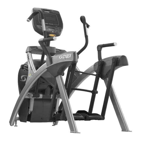
Summary of Contents for CYBEX Total Body 770AT
- Page 1 Assembly Instructions after Remanufactured Unit is Partly Assembled. Refer to Pages 32-39 for assembly of the remanufactured unit...
-
Page 2: 770At Assembly Procedure
770AT Assembly Procedure Tools Required Phillips screwdriver • Stubby Phillips screwdriver • 3/16” Allen wrench (supplied) • 7/32” Allen wrench (2) (supplied) • 9/16” Open end wrench (2) • The words “left” and “right” denote the user’s orientation. Two people will be required for this procedure. Read and understand all instructions thoroughly before assembling this unit. - Page 4 Verify contents of hardware pack See hardware pack listings and hardware pack contents. See Customer Service for contact information if any parts are missing. Item Quantity Part Number Description 600A-311 Flange Spacer BK030201 3/16” Allen Wrench BK030204 7/32” Allen Wrench HC700428 BHSCS .375-16 x 2.25”...
- Page 6 Lift and move unit 1. Remove large bolts and shipping supports. Keep package material on linkage arms at this time. This will protect the paint from scratching during assembly. 2. Grasp each rear support leg firmly and lift with one person on each side. 3. Lift the lower rear support legs using proper lifting methods so the front transport wheels are able to roll on floor.
- Page 7 Install accessory tray base 1. Place the accessory tray in position on the frame and route the iPod cable towards the back of the unit. Accessory Tray Base iPod Cable Frame Screws 2. Install the four screws using a Phillips screwdriver. Install accessory tray top 1. Place the accessory tray top in position on the accessory tray base and route the iPod cable through the notch in the accessory tray.
- Page 8 Install accessory tray bottom Install the grommet to the frame. Frame Grommet Install the accessory tray bottom to the accessory tray base with three screws using a Phillips screwdriver. Accessory Tray Bottom Accessory Tray Base Screw Screws (2)
- Page 9 Remove left and right handle assembly The left and right handle assemblies are shipped in rotated positions. The handle assemblies must be removed and rotated 180 degrees for proper setup and assembly. Shipping Position 1. Remove a screw and washer from the left handle assembly using two 7/32” Allen wrenches. Screw Washer Left...
- Page 10 7. Remove a screw and washer from the right handle assembly using two 7/32” Allen wrenches. Screw Washer Right Handle Pivot Pin Assembly 8. Slide pivot pin assembly out and remove right handle assembly. 9. Rotate right handle assembly 180 degrees. 10. Apply Loctite to threads inside the pivot pin and screw.
- Page 11 Install right linkage rod 1. Pivot right handle assembly up and slide right linkage rod onto right arm. Linkage Rod Flange Right Linkage Spacer Washer Loctite Screw Right Arm 2. Place a drop of Loctite onto the screw. 3. Install the screw, washer, linkage rod cap, and flange spacer using a 3/16” Allen wrench. 4. Tighten screw to a minimum of 90 in/lbs.
- Page 12 Connect contact heart rate cable 1. Plug right heart rate cable into main frame socket. Right Side Main Frame Shown Socket Heart Rate Wire Position plug so handle does not rub cable during operation. 2. Plug left heart rate cable into main frame socket. Install handrails.
- Page 13 3. Install the left inner rear cover with two screws using a Phillips screwdriver. Left Inner Rear Cover Screws (2) 4. Install the left outer rear cover with five screws using a Phillips screwdriver. Screws (2) Left Outer Rear Cover Screws (3) 5. Install the left top rear cover with five screws using a Phillips screwdriver.
- Page 14 6. Install the left inner and outer collars with two screws using a Phillips screwdriver. Collars are marked with an “L” on the inside and have a left and right side. Screws (2) “L” Left Outer Collar Left Inner Collar 7. Remove three locknuts from the right support leg using two 9/16”...
- Page 15 10. Install the right outer rear cover with five screws using a Phillips screwdriver. Screws (3) Right Outer Rear Cover Screws (3) 11. Install the right top rear cover with five screws using a Phillips screwdriver. Right Top Rear Cover Screws (5) 12. Install the right inner and outer collars with two screws using a Phillips screwdriver.
- Page 16 Attach foot pads Have one person lift the unit while a second person places a foot pad under each of the two back feet. Foot Pads (2) Level unit Confirm unit is on a level surface. If not, use a 9/16” open-end wrench to adjust the leveling feet up or down.


Need help?
Do you have a question about the Total Body 770AT and is the answer not in the manual?
Questions and answers