Dormakaba ED100 Installation Instructions Manual
Automatic swing door operators installation in overhead concealed header
Hide thumbs
Also See for ED100:
- Installation instructions manual (124 pages) ,
- Service manual (54 pages) ,
- Mounting instructions (52 pages)

Subscribe to Our Youtube Channel
Related Manuals for Dormakaba ED100


Summary of Contents for Dormakaba ED100
- Page 1 ED100/ED250 Automatic Swing Door Operators Installation in Overhead Concealed Header Installation Instructions DL4614-100 – 08-2018 | EN |...
- Page 2 ED100/ED250 OHC Installation Instructions Table of Contents Table of contents Table of contents Recommended tools and torque chart General information 12.1 Recommended tools ED100/ED250 OHC product description 12.2 Standard tightening torque Safety information 12.3 Drill bits ED100/ED250 OHC door configurations...
- Page 3 Install ED100/ED250 OHC operator Single door installation and hardware; LH side of header 30.1 Customer supplied single door 22.1 Install ED100/ED250 operator in LH side - installation of header 30.2 Prepare top of door for overhead arm 22.2 Install ED100/ED250 operator on 30.3...
-
Page 4: Table Of Contents
ED100/ED250 OHC Installation Instructions Table of Contents Install fixed stop, outswing doors 34.1 Install fixed stop, outswing doors Connect accessory wiring 35.1 Connect accessory wiring, single door 35.2 Connect accessory wiring, double doors ANSI/BHMA standards 36.1 A156.10 Power operated pedestrian doors 36.2... - Page 5 ED100/ED250 OHC Installation Instructions Blank page This page left intentionally blank ED100/ED250 DL4614-100 08-2018...
- Page 6 ED100/ED250 OHC Installation Instructions Chapter 1 1 General information 1.1 Installation instructions NOTICE This manual provides installation instructions for ED100/ED250 overhead concealed (OHC) automatic • Doors and jambs by customer. swing door operators used in single door and pair door •...
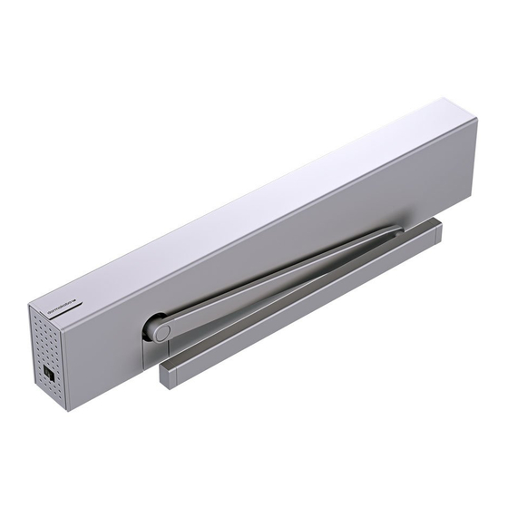
- Page 7 Fig. 2.2 ED100/ED250 OHC operator 2.2 Packaging The ED100 or ED250 operator is packaged in a header for overhead concealed (OHC) installation. For double swing doors, two ED100 or two ED250 operators are packaged in a single header.
- Page 8 WARNING 3.2 Door signage requirements. Proper signs and labels shall be applied and Crushing hazards at door closing edges! maintained on the door controlled by the ED100/ ED250 overhead concealed automatic swing door Fig. 3.1 Door closing edges operator as referenced in: •...
- Page 9 ED100/ED250 OHC Installation Instructions Chapter 4 4 ED100/ED250 OHC door configurations 4.1 ED100/ED250 OHC single door configurations Fig. 4.1.2 LH outswing RH outswing Fig. 4.1.1 LH inswing RH inswing 4.2 ED100/ED250 OHC double door configurations Fig. 4.2.1 Outswing Fig. 4.2.3 Inswing Fig.
- Page 10 5 ED100/ED250 OHC hardware - single door 5.1 OHC header and overhead arm configurations Fig. 5.1.1 ED100/ED250 OHC header, LH outswing Fig. 5.1.3 ED100/ED250 OHC header, RH outswing 1.2 Header, RH outswing Fixed stop Overhead arm Reference Para. 17.7 for 1.1 Header, LH...
- Page 11 10 Jamb bracket 115 Vac power cable extension cable End cap 5.3 ED100/ED250 OHC operator Fig. 5.3.1 OHC ED100/ED250 operator - header orientation for RH outswing or LH inswing OHC operator OHC mounting plate Control board Spring tension adjustment...
- Page 12 ED100/ED250 OHC Installation Instructions Chapter 5 5.4 ED100/ED250 OHC single door hardware package Fig. 5.4.1 115 Vac power module Fig. 5.4.5 115 Vac power cable PCB holder assembly DC4630-010 2.1 Power off/on switch 2.2 115 Vac connection Fig. 5.4.6 115 Vac power extension cable circuit board 2.3 Velcro...
- Page 13 ED100/ED250 OHC Installation Instructions Chapter 5 Fig. 5.4.13 Overhead arm kit DK4651-010 Fig. 5.4.18 9 mm axle extension kit Arm, OH center hung Hex bolt, 1/4-20 x 1", gr5, zinc Lock washer, 1/4" 9 mm axle extension Fig. 5.4.19 Breakout switch DK4638-010;...
- Page 14 ED100/ED250 OHC Installation Instructions Chapter 6 6 ED100/ED250 OHC hardware - double doors 6.1 OHC header and overhead arm configurations Fig. 6.1.1 Pair outswing 1.1 Header, pair outswing Overhead arm Fixed stop Reference Para. 17..7 for alternative fixed stop.
- Page 15 Fig. 6.2.5 Pair inswing header assembly example 6.3 ED100/ED250 OHC operator Fig. 6.3.1 OHC ED100/ED250 operator orientation - RH side of header mounting OHC operator OHC mounting plate Control board Spring tension...
- Page 16 ED100/ED250 OHC Installation Instructions Chapter 6 6.4 ED100/ED250 OHC pair door hardware package Fig. 6.4.1 115 Vac power module Fig. 6.4.7 115 Vac power cable PCB holder assembly DC4630-010 2.1 Power off/on switch 2.2 115 Vac connection Fig. 6.4.8 115 Vac power extension cable circuit board 2.3 Velcro...
- Page 17 ED100/ED250 OHC Installation Instructions Chapter 6 Fig. 6.4.15 Fixed stop DK4646; Fig. 6.4.20 Breakout switch DK4638-010; outswing door inswing door Fixed stop DC4643- 1.1 Backing plate DC4644-010 Breakout switch DK4638 2.1 Mounting plate 2.2 1/4-20 x 1/2" Phillips flat head undercut 2.3 #8 x 5/8"...
- Page 18 ED100/ED250 OHC Installation Instructions Chapter 7 7 ED100/ED250 OHC header assembly 7.1 ED100/ED250 OHC single door header example Fig. 7.1.1 ED100/ED250 OHC header and operator assembly, LH outswing Reference Chapter 26 for 115 Vac customer connection OHC header, LH 2.2 Control board...
- Page 19 ED100/ED250 OHC Installation Instructions Chapter 7 7.2 ED100/ED250 OHC pair doors header example Fig. 7.2.1 ED100/ED250 OHC header and operator assembly; outswing 11 115 Vac power cable OHC pair header, Low voltage wiring 115 Vac power Low voltage wiring...
- Page 20 ED100/ED250 OHC Installation Instructions Chapter 8 8 Technical data 8.1 ED100/ED250 Technical data 8.1.1 Required operating conditions 8.1.4 Outputs Maximum wire size Ambient temperature 5 to 122 °F 16 AWG Connector plug 1/16” Suitable for dry Relative air humidity:...
- Page 21 Note 1 Note 2 Full energy / low energy Speeds automatically limited depending on door weight, • FE: ED100/ED250 configured for full energy. set during learn cycle. • LE: ED100/ED250 configured for low energy. 9 Operational mode overview 9.1 ED100/ED250 door closer modes 9.1.1 Automatic mode...
- Page 22 ED100/ED250 OHC Installation Instructions Chapter 10 10 User interface 10.1 ED100/ED250 OHC operator user interface Fig. 10.1.1 OHC ED100/ED250 operator - header orientation for LH outswing or RH inswing RH operator 4 button keypad and 2 digit display 10.2 4 button keypad and display Fig.
- Page 23 10.4.1 RJ45 panel dormakaba • Supplied on double door installations. handheld • RJ45 cable connects panel to second ED100/ED250 RJ45 panel operator in header for dormakaba handheld connection. 10.5 Operator status LEDs 10.5.1 Operator status LEDs Fig. 10.5.1 Operator status LEDs...
- Page 24 ED100/ED250 OHC Installation Instructions Chapter 11 11 System accessories 11.1 System accessory electrical connections, overhead concealed header Fig. 11.1.1 Electrical connections, single door External program switch, mechanical 3 x 12 AWG 115 Vac power External program switch, electronic Key switch...
- Page 25 ED100/ED250 OHC Installation Instructions Chapter 11 11.3 ED100/ED250 terminal board interface Fig. 11.3.1 Terminal board electrical connections Green LED (Para. 10.5) Night- Activation inputs Yellow LED (Para. 10.5) Interior Exterior bank Safety sensors input Red LED (Para. 10.5) DCW bus...
- Page 26 ED100/ED250 OHC Installation Instructions Chapter 12 12 Recommended tools and torque chart 12.1 Recommended tools Fig. 12.1.1 Recommended tools T-handle hex key, 5 mm Hex keys, 2.5 mm, 3 mm, 5 mm Screwdriver, flat blade Door pressure gauge, 0 to 35 ft - lbf...
- Page 27 ED100/ED250 OHC Installation Instructions Chapter 13 13 ED100/ED250 door signage 13.1 Full energy operator 13.2 Low energy operator 13.1.1 Overview 13.2.1 Overview Signage and warnings are specified in ANSI /BHMA Signage and warnings are specified in ANSI /BHMA A156.10, American National Standard for power A156.19, American National Standard for power assist...
- Page 28 ED100/ED250 OHC Installation Instructions Chapter 13 13.3 Door signage, full energy single swing doors Fig. 13.3.1 One decal, one way traffic Fig. 13.3.3 Once decal, two way traffic Approach Non-approach Approach Approach, door swing side DO NOT AUTOMATIC CAUTION...
- Page 29 ED100/ED250 OHC Installation Instructions Chapter 13 13.5 Door signage, full energy double swing doors Fig. 13.5.1 One way traffic, approach side Fig. 13.5.4 One way traffic, door swing side DO NOT DO NOT ENTER ENTER AUTOMATIC AUTOMATIC DOOR DOOR...
- Page 30 ED100/ED250 OHC Installation Instructions Chapter 13 13.6 Door signage, low energy double swing doors, initiation of door operation Fig. 13.6.1 Knowing act device Fig. 13.6.3 Knowing act device, opposite side AUTOMATIC AUTOMATIC AUTOMATIC AUTOMATIC CAUTION CAUTION CAUTION CAUTION DOOR...
- Page 31 ED100/ED250 OHC Installation Instructions Chapter 13 13.7 Door signage, full energy double egress swing doors Fig. 13.7.1 OHC RH double egress Fig. 13.7.4 OHC LH double egress Fig. 13.7.2 RH double egress, interior side Fig. 13.7.5 LH double egress, interior side...
- Page 32 INFORMATION that should be performed daily on automatic swing SAFETY INFORMATION Low Energy Swinging door controlled by an ED100/ED250 overhead concealed Automatic Swinging Doors Doors operator configured for full energy operation. These minimum safety checks, 13.9.2 Safety information label location...
- Page 33 ED100/ED250 OHC Installation Instructions Blank page This page left intentionally blank. ED100/ED250 DL4614-100 08-2018...
- Page 34 ED100/ED250 OHC Installation Instructions Chapter 14 14 ED100/ED250 OHC installation template 14.1 Header installation Fig. 14.1.1 Single door LH outswing header Width between jambs = header width + 2 x end cap thickness (.08” each) 3 3/4” End Cap...
- Page 35 ED100/ED250 OHC Installation Instructions Chapter 14 14.2 Bottom pivot, floor installation Fig. 14.2.1 Section view D-D and E-E Pivot, floor mounted Jamb Jamb Finished floor surface Jamb Jamb Finished floor surface Fig. 14.2.2 Section view D-D and E-E Pivot, floor mounted 1.1 Fastener:...
- Page 36 ED100/ED250 OHC Installation Instructions Chapter 14 14.3 Program panel jamb cutout Fig. 14.3.1 Program panel jamb cutout 1” R 1/8” TYP 1/2” 1 5/8” 1 3/8” 3 3/4” 2 3/4” 3 1/4” 2 X #36 drill Program panel cable 1 3/4”...
- Page 37 ED100/ED250 OHC Installation Instructions Chapter 14 14.4 RJ45 panel jamb cutout, double doors Fig. 14.4.1 RJ45 panel for dormakaba handheld 1” R 1/8” TYP Jamb 1/2” 1 5/8” 1 3/8” 3 3/4” 2 3/4” 3 1/4” 2 X #36 drill RJ45 connector 1 3/4”...
- Page 38 ED100/ED250 OHC Installation Instructions Chapter 16 16 Customer installed door jambs 16.1 Check jamb installation dimensions Fig. 16.1.1 Door opening, jambs installed Fig. 16.1.2 Checking floor high point Width between jambs Frame opening height Customer jamb Level Customer jamb...
- Page 39 ED100/ED250 OHC Installation Instructions Chapter 16 16.2 Check jambs for plumb, level, and square Fig. 16.2.1 Single door frame Equal distance Center of door opening 16.2.1 Check door frame for plumb, level and square. CAUTION 1. Use level to check jambs for level and plumb.
- Page 40 ED100/ED250 OHC Installation Instructions Chapter 16 16.3 Drill holes in jambs for header mounting and for wiring into header 16.3.1 Mark holes in jambs for header. TIPS AND RECOMMENDATIONS 1. Using template dimensions, mark four jamb bracket mounting hole locations (1) in each jamb.
- Page 41 ED100/ED250 OHC Installation Instructions Chapter 16 16.4 Program switch panel jamb cutout 16.4.1 Program switch panel cutout and CAUTION mounting holes. 1. Cutout jamb, drill mounting holes for Mounting holes for program program switch panel. switch panel flat head screws Reference Para.
- Page 42 ED100/ED250 OHC Installation Instructions Chapter 17 17 Header preparation 17.1 Remove ED100/ED250 operator from mounting plate: right side of header mounting example Fig. 17.1.1 ED100/ED250 operator fastened to mounting plate M6 x 10 SHCS M6 x 20 SHCS Mounting plate 5 mm T handle hex key Fig.
- Page 43 ED100/ED250 OHC Installation Instructions Chapter 17 17.2 Install ED100/ED250 OHC mounting plate in right side of header Fig. 17.2.1 OHC header, ED100/ED250 operator mounting on right side ED100/ED250 OHC header 1.1 Jamb bracket Header track, 1/2" x 23 1/2"...
- Page 44 ED100/ED250 OHC Installation Instructions Chapter 17 17.3 Install ED100/ED250 OHC mounting plate in left side of header Fig. 17.3.1 OHC header, ED100/ED250 operator mounting on left side ED100/ED250 OHC header 1.1 Jamb bracket Header track, 1/2" x 23 1/2"...
- Page 45 4 sets 3,4 PCB holder assembly, Terminal PCB DC4630 Low voltage terminal PCB Fig. 17.4.3 Terminal PC board module installed in header; ED100/ED250 operator on left 1/4-20 x 1/2" SBHCS 1/4" square nut, installed in header track OHC mounting plate installed on left Fig.
- Page 46 Chapter 17 17.5 Double header: Install ED100/ED250 OHC mounting plates and Terminal PC boards Fig. 17.5.1 OHC double header, ED100/ED250 OHC operator mounting plate and Terminal PC boards, both sides ED100/ED250 OHC Terminal PC board double header, module, LH ED100/...
- Page 47 ED100/ED250 OHC Installation Instructions Chapter 17 Fig. 17.6.3 Header breakout switch cutout Fig. 17.6.5 Header breakout switch and mounting holes, LH inswing installed, LH inswing Panic breakout switch Breakout mounting plate 1/4-20 x 1/2" Phillips flat head (undercut) Cutout and...
- Page 48 ED100/ED250 OHC Installation Instructions Chapter 19 19 Install OHC header - single door 19.1 Header installation 19.1.1 Review prior to installing header. Fig. 19.1.1 Jambs installed in door opening 1. Jamb installation and floor level and flatness verified. •...
- Page 49 ED100/ED250 OHC Installation Instructions Chapter 19 19.2 Header installation ED100/ED250 OHC operator on right hand side of header Fig. 19.2.1 Header mounting hardware, LH Fig. 19.2.2 Header mounting hardware, RH side of header internal view side of header internal view...
- Page 50 Refer to Chapter 19 Install OHC Header - single door. 1. Instructions are contained for header mounting with: • ED100/ED250 OHC operator on header right side • ED100/ED250 OHC operator on header left side 2. Fasteners for securing header to jambs are referenced.
- Page 51 ED100/ED250 OHC Installation Instructions Chapter 21 21 Remove ED100/ED250 protective film strips 21.1 Remove protective film strips from ED100/ED250 operator Fig. 21.1.1 Operator protective film strips, M6 fastener locations M6 x 10 SHCS M6 x 20 SHCS Protective film strip 21.1.1 Remove protective film strips.
- Page 52 ED100/ED250 OHC Installation Instructions Chapter 22 22 Install ED100/ED250 OHC operator and hardware; LH side of header 22.1 Install ED100/ED250 operator in LH side of header Fig. 22.1.1 Mounting plate orientation for LH side of header ED100/ED250 OHC mounting plate,...
- Page 53 ED100/ED250 OHC Installation Instructions Chapter 22 22.3 Install ED100/ED250 OHC operator hardware Fig. 22.3.1 115 Vac power module PCB holder assembly DC4630 2.1 Power off/on switch 2.2 115 Vac connection circuit board 2.3 Velcro Fig. 22.3.2 115 Vac power module installed 22.3.1 Install 115 Vac Power Module.
- Page 54 23 Install ED100/ED250 OHC operator and hardware; RH side of header 23.1 Install ED100/ED250 operator in RH side of header Fig.23.1.1 Header with ED100/ED250 OHC mounting plate and low voltage terminal module ED100/ED250 OHC mounting plate, right side of header...
- Page 55 ED100/ED250 OHC Installation Instructions Chapter 23 23.3 Install ED100/ED250 OHC operator hardware Fig. 23.3.1 115 Vac power module PCB holder assembly DC4630 2.1 Power off/on switch 2.2 115 Vac connection circuit board 2.3 Velcro Low voltage terminal module Fig. 23.3.2 115 Vac power module installed 23.3.1 Install 115 Vac Power Module.
- Page 56 24 Install ED100/ED250 OHC operators and hardware; double door header 24.1 Install ED100/ED250 operators in header Fig.24.1.1 Header with ED100/ED250 OHC operators and hardware installed, double egress example Fig.24.1.2 Header RH door with ED100/ED250 OHC operator and hardware installed ED100/ED250 OHC operator 1.1 Control board...
- Page 57 ED100/ED250 OHC Installation Instructions Chapter 24 24.3 Install power cable between ED100/ED250 OHC operators Fig.24.3.1 115 Vac power cable installation 6.1, 7.1 6.1, 7.1 1.3 ED100/ED250 OHC 115 Vac power 5.1 Main power cable 6.1 Self tapping screw Mounting holes and...
- Page 58 ED100/ED250 OHC Installation Instructions Chapter 25 25 Install floor pivot 25.1 Install floor pivot Fig. 25.1.1 Bottom pivot assembly NOTICE DC0735-020 Plug, 1 1/2" Double doors Plug, 10 mm Install floor pivots at both jambs Door pivot using steps in Para. 25.1.1 through Screw pack 25.1.3...
- Page 59 1. Thread M8 SHCS into drive axle using ED100/ED250 OHC 5 mm hex key. axle M8 SHCS, custom 2. Check plumb of ED100/ED250 OHC axle to floor pivot. CAUTION Plumb must be checked to insure floor pivot is in alignment with ED100/ED250 drive axle.
- Page 60 TIGHTEN MAINS TERMINAL TO 5-7 in-lb Use Copper Conductors ONLY Routing and connection of 115 VAC wiring to ED100/ED250 OHC Fig. 26.1.2 115 Vac connection; ED100/ operator must be performed by a ED250 operator left side of qualified person! header...
- Page 61 ED100/ED250 OHC Installation Instructions Chapter 26 Fig. 26.1.5 115 Vac terminal block; ED100/ED250 OHC operator on LH side of header Fig. 26.1.6 115 Vac terminal block; ED100/ED250 OHC operator on RH side of header Fig. 26.1.7 115 Vac terminal block; ED100/ED250 OHC double door header 5.1 Main power cable...
- Page 62 1.1 Comm port for dormakaba handheld 1.2 4 strand ribbon cable, 10' 1.3 RJ45 port Fig. 27.1.2 ED100/ED250 OHC operator with program switch cables installed 1.2 4 strand ribbon cable, 10' 1.3 Vertical RJ45 connector, dormakaba handheld RJ45 communication cable, 10'...
- Page 63 Fig. 27.2.4 RJ45 Panel back view 1.1 Comm port for dormakaba handheld 1.3 RJ45 port RJ45 panel DX4604-031 Fig. 27.2.2 ED100/ED250 OHC inactive operator with RJ45 cable installed 1.3 RJ45 port, dormakaba handheld RJ45 communication cable, 10' DX4607-020 RJ 45 connector...
- Page 64 ED100/ED250 OHC Installation Instructions Chapter 28 28 Install axle extension and overhead arm 28.1 Install axle extension and overhead arm Fig. 28.1.1 9 mm axle extension and arm installation NOTICE Double doors: Install axle extensions and arms at both ED100/ED250 OHC operators using steps in Para.
- Page 65 ED100/ED250 OHC Installation Instructions Chapter 29 29 System setup for single door installation 29.1 Set braking circuit plug position Fig. 29.1.1 Braking circuit socket and plug views Braking circuit plug Braking circuit 3 pin socket User interface Power fail closing speed potentiometer 29.1.1 Set braking circuit plug position.
- Page 66 Door width is set in increments of 100 mm (4"): Measured width of 1000 mm (39.4") = Tb value of "10". ED100/ED250: [914 - 1219 mm] 36" - 48". 29.2.3 ED100/ED250 OHC door widths and Tb parameter values Fig.29.2.1 OHC door Door width measurement...
- Page 67 ED100/ED250 OHC Installation Instructions Chapter 29 29.4 Set operator spring tension Fig. 29.4.1 Spring tension adjustment, ED100/ED250 operator on LH side of header example ED100/ED250 OHC header (shown transparent) ED100/ED250 operator Spring tension adjustment T handle hex key, 5 mm 29.4.1 Spring tension setting revolutions.
- Page 68 ED100/ED250 OHC Installation Instructions Chapter 29 29.5 ED100/ED250 OHC firmware; viewing and changing parameters 29.5.1 Firmware version 2. Use 4 button keypad as outlined in Steps 1 through 8 to view or change parameter values. TIPS AND RECOMMENDATIONS Fig. 29.5.3 4 button keypad, 2 digit display •...
- Page 69 ED100/ED250 OHC Installation Instructions Chapter 29 29.6 ED100/ED250 OHC configuration parameters 29.6.1 Configuration parameters, detail Bold numbers; factory setting Reveal depth Parameter and value Reveal is set in increments of range, factory setting Parameter description ED100/ 10 mm (3/8"), "3" = 30 mm (1 1/8").
- Page 70 ED100/ED250 OHC Installation Instructions Chapter 29 29.7 Set configuration parameters 29.7.1 Set parameter AS, installation type. Fig. 29.7.1 4 button keypad, 2 digit display Step 1 Press and hold PRG button greater Four button keypad Press than 3 seconds to enter program Two digit display mode, AS parameter is displayed.
- Page 71 ED100/ED250 OHC Installation Instructions Chapter 29 29.8 ED100/ED250 OHC power on Fig. 29.8.1 Program switch 29.8.1 Conditions prior to commissioning. 1. 115 Vac branch circuit to operator is energized. Program switch, 2. Operator motor is cold. 3 position CAUTION Motor must be cold for learning cycle! Fig.
- Page 72 ED100/ED250 OHC Installation Instructions Chapter 29 29.9 Perform partial learning cycle to rotate arm to door installation position 29.9.1 Initiate learning cycle to rotate arm. TIPS AND RECOMMENDATIONS Block arm at door closed position. Hold block in place [Use caution!], or •...
- Page 73 ED100/ED250 OHC Installation Instructions Chapter 29 Fig. 29.9.3 Overhead arm at zero degree closed position. 29.9.3 Door overhead arm configurations. Fig. 29.9.5 LH outswing Header cover Fig. 29.9.6 RH outswing Fig. 29.9.4 Overhead arm at 70 degree position for door installation;...
- Page 74 CAUTION Jamb edge to floor pivot centerline distance: 3 3/4". Reference Chapter 14, Installation Template, Para. 14.2. 3. ED100/ED250 OHC operator axle to floor pivot plumb checked (Chapter 25). 4. Door bottom pivot hardware installed in floor by customer. ED100/ED250...
- Page 75 ED100/ED250 OHC Installation Instructions Chapter 30 30.2 Prepare top of door for overhead arm Fig. 30.2.1 Overhead center hung arm 30.2.1 Prepare door for overhead arm. DC4625-010 1. Mortise top of door for overhead arm using dimensions referenced in Fig. 30.2.2 and 30.2.3.
- Page 76 ED100/ED250 OHC Installation Instructions Chapter 30 30.3 Prepare door for bottom door pivot and install pivot Fig. 30.3.1 Bottom door pivot dimensions Fig. 30.3.3 Bottom door pivot 5 5/16” R 21/32” 7/8” 7/8” 3 1/8” 1 5/16” 3/4” Ø 0.26”...
- Page 77 ED100/ED250 OHC Installation Instructions Chapter 30 30.5 Hang door 30.5.1 Hang door. RH inswing example. Fig. 30.5.1 Door positioned for installation TIPS AND RECOMMENDATIONS A second person is recommended for door installation! WARNING Hand pinch point and crushing hazards during door install.
- Page 78 ED100/ED250 OHC Installation Instructions Chapter 30 30.5.4 Secure door to overhead arm. Fig. 30.5.5 Securing door to overhead arm 1. Insert 1/4" lock washer onto each 1/4" x 1" hex bolt and thread bolts into door clearance holes. •...
- Page 79 ED100/ED250 OHC Installation Instructions Chapter 30 30.6 Perform learning cycle CAUTION Press and hold down button until display changes. Learning cycle must be performed while Step 3 • Door performs several movements Press ED100/ED250 motor is cold! and display shows a sequence of symbols.
- Page 80 ED100/ED250 OHC Installation Instructions Chapter 30 30.7 Set power fail closing speed Fig. 30.7.1 Power fail closing speed potentiometer, ED100/ED250 operator on RH side of header Power fail closing speed potentiometer Control board Power switch 30.7.1 Power fail closing speed potentiometer.
- Page 81 ED100/ED250 OHC Installation Instructions Chapter 31 31 System setup for double door installation 31.1 Set braking circuit plug position for each ED100/ED250 operator Fig. 31.1.1 Braking circuit socket and plug views Braking circuit plug Braking circuit 3 pin socket...
- Page 82 Door width is set in increments of 100 mm (4"): Measured width of 1000 mm (39.4") = Tb value of "10". LH door ED100/ED250: [914- 1219 mm] 36" - 48" 31.2.3 ED100/ED250 OHC door widths and Tb parameter values Fig.31.2.1 OHC door Door width measurement Door width measurement...
- Page 83 ED100/ED250 OHC Installation Instructions Chapter 31 31.4 Set operator spring tension for each ED100/ED250 operator Fig. 29.4.1 Spring tension adjustment, ED100/ED250 operator on LH side of header example ED100/ED250 OHC header (shown transparent) ED100/ED250 operator Spring tension adjustment T handle hex key, 5 mm 31.4.1 Spring tension setting revolutions.
- Page 84 ED100/ED250 OHC Installation Instructions Chapter 31 31.5 ED100/ED250 OHC firmware; viewing and changing parameters 31.5.1 Firmware version 2. Use 4 button keypad as outlined in Steps 1 through 8 to view or change parameter values. TIPS AND RECOMMENDATIONS Fig. 31.5.3 4 button keypad, 2 digit display •...
- Page 85 ED100/ED250 OHC Installation Instructions Chapter 31 31.6 ED100/ED250 OHC configuration parameters 31.6.1 Configuration parameters, detail Bold numbers; factory setting Reveal depth Parameter and value ED100/ range, factory setting Parameter description ED250 • Overhead concealed header: = bold. Factory setting...
- Page 86 ED100/ED250 OHC Installation Instructions Chapter 31 31.7 Set configuration parameters; double door 31.7.1 Set parameter AS, installation type for each 31.7.2 Set parameter Tb, door width for each ED100/ ED100/ED250 operator. ED250 operator. Reference Para. 31.1.2 for door configurations.
- Page 87 ED100/ED250 OHC Installation Instructions Chapter 31 NOTICE Perform steps in Paragraphs 31.8 and 31.9 for each ED100/ED250 operator. 31.8 ED100/ED250 OHC power on 31.8.1 Conditions prior to commissioning. Fig. 31.8.1 Program switch 1. 115 Vac branch circuit to operator is energized.
- Page 88 ED100/ED250 OHC Installation Instructions Chapter 31 31.9 Perform partial learning cycle to rotate arm to door installation position for each ED100/ED250 operator 31.9.1 Initiate learning cycle to rotate arm. TIPS AND RECOMMENDATIONS Block arm at door closed position. Hold block in place [Use caution!], or •...
- Page 89 ED100/ED250 OHC Installation Instructions Chapter 31 Fig. 31.9.3 Double door RH arm inswing example Fig. 31.9.7 Outswing Fig. 31.9.8 Inswing Fig. 31.9.4 Double door LH arm inswing example Fig. 31.9.9 LH double egress Fig. 31.9.10 RH inswing Fig. 31.9.5 Double door inswing example; arms rotated 70 degrees...
- Page 90 Template, Para. 14.2. Door installation must meet ANSI/BHMA standards as well as any applicable local 3. ED100/ED250 OHC operator axle to floor pivot building codes. plumb checked for both doors (Chapter 25). 4. Bottom pivot hardware installed in floor by customer for both doors.
- Page 91 ED100/ED250 OHC Installation Instructions Chapter 32 32.2 Perform learning cycle for each ED100/ED250 operator 32.2.1 Perform learning cycle. CAUTION Press and hold down button until display changes. Double doors must be hung; reference Para. Step 3 • Door performs several movements Press 32.1...
- Page 92 ED100/ED250 OHC Installation Instructions Chapter 32 32.3 Set power fail closing speed for each ED100/ED250 operator 32.3.1 Set power fail closing speed. Fig. 32.3.1 Power fail closing speed potentiometer, ED100/ED250 operator on RH side of header Power fail closing speed potentiometer Control board Power switch 32.3.1 Power fail closing speed...
- Page 93 Chapter 33 33 Double door parameters, comm cable CAUTION Both doors must have full learning cycles completed; reference Chapter 32. 33.1 Set ED100/ED250 operator parameters for double door operation NOTICE Door type If using BEA LZR Microscan, Appendix A2.1 & Parameter A2.2, dL parameter must be "0"...
- Page 94 Step 4 Step 8 Press "00" starts flashing. Press Exits program mode. Operator is ready for operation. 33.2 Connect communication cable between ED100/ED250 operators Fig. 33.2.1 Double door operators, communication cable ED100/ED250 operator RJ45 jack (horizontal) for communication cable Communication cable DX3485-030 *Ribbon cables not shown.
-
Page 95: Install Fixed Stop, Outswing Doors
ED100/ED250 OHC Installation Instructions Chapter 34 34 Install fixed stop, outswing doors 34.1 Install fixed stop, outswing doors Fig. 34.1.1 Fixed stop assembly DC4643-01_ TIPS AND RECOMMENDATIONS Fixed stop Install on outswing door if Fixed 1/4-20 x 1 1/4"... - Page 96 ED100/ED250 OHC Installation Instructions Chapter 34 Fig. 34.1.5 Fixed stop mounting holes, Fig. 34.1.7 Fixed stop installation, LH outswing LH outswing Fixed stop 1/4-20 x 1 1/4" FHMS 3/4" flat washer 1/4-20 nut Backing plate, fixed stop DC4644 Header, LH outswing Fixed stop mounting holes, 9/32"...
-
Page 97: Connect Accessory Wiring
ED100/ED250 OHC Installation Instructions Chapter 35 35 Connect accessory wiring 35.1 Connect accessory wiring, single door Fig. 35.1.1 Accessory wiring terminal board, ED100/ED250 operator on left example Low voltage terminal board module 35.1.1 Connect accessory wiring. 35.1.2 Panic breakout switch wiring. -
Page 98: Ansi/Bhma Standards
The following table references portions of content from ANSI/BHMA A156.10. Refer to the standard, available through ANSI or BHMA for additional information. Standard material reprinted with BHMA permission. Reference ED100/ED250 service manual for additional parameter detail. 36.1.1 Door measurements, power operated swing door ED100/ED250 Parameter A156.10 standard... -
Page 99: A156.19 Low Energy Power Operated Doors
The following table references portions of content from ANSI/BHMA A156.19. Refer to the standard, available through ANSI or BHMA for additional information. Standard material reprinted with BHMA permission. Reference ED100/ED250 service manual for additional parameter detail. 36.2.1 Door measurements, low energy power operated door ED100/ED250 Parameter A156.19 standard... -
Page 100: Install Door Signage, Header Cover
ED100/ED250 OHC Installation Instructions Chapters 36 and 37 36.2.2 A156.19, Table I: Minimum opening and closing times. "W" door weight, pounds "D" door width, inches 3.0 s 3.5 s 3.5 s 3.0 s 3.0 s 3.5 s 4.0 s 4.0 s... - Page 101 ED100/ED250 OHC Installation Instructions Blank page This page left intentionally blank. ED100/ED250 DL4614-100 08-2018...
-
Page 102: Upgrade Cards
38.1 Upgrade cards 38.2 Container module 39.1.1 Upgrade card installation 38.2.1 Container module dormakaba USA Inc. upgrade cards can be used to expand the • The first upgrade card installed becomes range of functions of the ED100/ED250 operator. the container module. -
Page 103: Installing Upgrade Cards
ED100/ED250 OHC Installation Instructions Chapter 38 38.3 Installing upgrade cards 38.3.1 Set program switch to CLOSE. 38.3.3 Installing additional upgrade cards Upgrade card slot Professional Set program switch to Close. upgrade card 1. Remove container Container module module from upgrade Program switch card slot. -
Page 104: Maintenance
39 Maintenance 39.1 ED100/ED250 environment and cleaning Table 39.1.1 Operator environmental requirements 39.1.1 ED100/ED250 environmental requirements. ED100/ED250 overhead concealed header assembly is Ambient temperature 5 to 122 °F designed to operate on an interior building surface under the specifications shown in Table 39.1.1. -
Page 105: Overhead Arm And Bottom Door Pivot
ED100/ED250 OHC Installation Instructions Chapter 39 39.3 Overhead arm and bottom door pivot 39.3.1 Check overhead arm and Fig. 39.3.1 Axle extension and arm installation connection to drive axle. Arm, overhead 1. Remove door(s). center hung • Door(s) must be removed to check... -
Page 106: Appendix A - Parameters
ED100/ED250 OHC Installation Instructions Appendix A Appendix A - Parameters A1.1 Configuration Parameters - Detail Parameter and value Parameter and value range, factory setting Parameter description range, factory setting Parameter description = bold. = bold. Installation type Door width ED100/ •... -
Page 107: A1.2 Parameters
ED100/ED250 OHC Installation Instructions Appendix A A1.2 Parameters Configuration Driving parameters Description Description Parameters Input 4/4a and X3, 1G 24V locking Installation type device output configuration Cycle counter, number displayed * 10000 Reveal depth Delete error log Door width... -
Page 108: A1.3 Driving Parameters - Detail
ED100/ED250 OHC Installation Instructions Appendix A A1.3 Driving Parameters - Detail Value Factory Parameter Units Description range setting Opening speed, automatic mode 1. Opening speed refers to automatic mode, speed can be adjusted using this parameter. ED100 2. Internal monitoring system checks if parameter setting is admissible. If setting °/s... - Page 109 ED100/ED250 OHC Installation Instructions Appendix A Value Factory Parameter Units Description range setting Safety sensor test Safety sensor parameter ST must be set to sensors used and if they are active-high or active-low. See E 04 safety sensor test error, Appendix B.4.
- Page 110 ED100/ED250 OHC Installation Instructions Appendix A Value Factory Parameter Units Description range setting Power reserve module SVP-PR 12 test Test off 1. SVP-PR 12 power reserve module test is performed once every 24 hours, or 10 minutes after AC power has been turned on. In event of an error: •...
- Page 111 ED100/ED250 OHC Installation Instructions Appendix A Value Factory Parameter Units Description range setting Push & Go 1. Parameter is activated. 2. Automatic opening of door is started when door is manually moved 4° out of the 0 - 1 closed position.
- Page 112 (v1.9). 1. Status relay activated when door is opened further than opening angle parameter OA, set during learning cycle. 2. Parameter OA value can only be changed using dormakaba handheld or by performing another learning cycle. Locking device output configuration;...
- Page 113 ED100/ED250 OHC Installation Instructions Appendix A Value Factory Parameter Units Description range setting Factory setting level Parameter SL is used to determine what data will be reset during factory setting process. Standard factory settings • Program switches OFF. •...
- Page 114 ED100/ED250 OHC Installation Instructions Appendix A Value Factory Parameter Units Description range setting Power assist function (v1.7) 1. Force setting for Power assist function. 2. Power assist function only available with hd parameter = 1, manual mode. 3. "0"; power assist function OFF; power assist function enabled for available values greater than 0.
- Page 115 COM 1 configuration interface Interface programmed for communication with dormakaba handheld. 0 - 1 Interface programmed for use with dormakaba TMS Soft control software. Back check when door opened manually 1. Angle after which door is braked when manually opened.
- Page 116 ED100/ED250 OHC Installation Instructions Appendix A Value Factory Parameter Units Description range setting Door thickness 1. Parameter is entered in mm. 0 - 99 2. Door thickness affects measured door opening angle. 3. Parameter Td enables a more accurate door width to be entered, if required.
-
Page 117: Appendix B - Troubleshooting
E 0 through E 9. 2. The latest error message is always stored in error B.1.3 User information display. memory location E 0: User interface display, or dormakaba handheld displays: • As soon as another error occurs, the existing error • Information ln codes stored in E 0 will be moved to E 1 and the latest error •... -
Page 118: Red Led Status Codes
ED100/ED250 OHC Installation Instructions Appendix B B.2 Red LED status codes B.2.1 Red LED status codes. Red LED status Display Description Control unit has detected error, Steady flashing emergency mode activated. On steady ln 11 Hold-open device triggered. Flashing 2 times E 02 Locking device error. -
Page 119: Troubleshooting Chart, "Ln" Codes
ED100/ED250 OHC Installation Instructions Appendix B B.3 Troubleshooting chart, "ln" codes B.3.1 Troubleshooting chart, information messages. Display Description Troubleshooting information messages Sustained operation on a door with an obstruction can result in damage to drive. 1. Object or person obstructing door movement. -
Page 120: Troubleshooting Chart, "E" Code
4. Check for activation of the test at the safety sensors. EEPROM error • Internal memory check could 1. Using dormakaba handheld, reload current firmware to Flashing not be completed. reinitialize system. E 12 12 x •... - Page 121 ED100/ED250 OHC Installation Instructions Appendix B B.4.1 Troubleshooting chart, "E" codes (continued). • Description Display Red LED Troubleshooting error codes Overcurrent detection 1. Motor is consuming too much power, check for any external Flashing • Motor is consuming more causes.
-
Page 122: Appendix C - Dormakaba Handheld
ED100/ED250 OHC Installation Instructions Appendix C Appendix C - dormakaba handheld C.1 dormakaba handheld C.1.2 Handheld key functions. 1. OFF ON, switches Handheld on or off. Fig. C.1.1 dormakaba handheld 2. Function keys F1 - F3, trigger functions shown in Off/On key bottom line of display (e.g., "RPT"... -
Page 123: Configuration Parameters
ED100/ED250 OHC Installation Instructions Appendix C NOTICE Parameters and detail may change depending on firmware version. C.2 Configuration parameters "#" refers to reference numbers in Parameter list, Appendix C.2.1 Configuration parameters Parameter and Parameter and Description / Selections Description / Selections... -
Page 124: Driving Parameters
ED100/ED250 OHC Installation Instructions Appendix C C.2.1 Configuration parameters Parameter and Description / Selections default Parameter and Description / Selections Manual mode on. default Manual mode Manual mode disabled. NO contact; night- bank function Normal* Power assist triggered while contact... -
Page 125: Special Functions (Upgrade Cards)
ED100/ED250 OHC Installation Instructions Appendix C C.4 Special functions (Upgrade cards) C.4.1 Special functions (upgrade cards) Parameter and Parameter and Description / Selection Description / Selection default default • locked: not available locked Upgrade • unlocked: available, not active... -
Page 126: Diagnostics
ED100/ED250 OHC Installation Instructions Appendix C C.5 Diagnostics C.5.1 Diagnostics Parameter name Description Setting Parameter name Description Setting FW vers BM Displays firmware (FW) x.x y y (e.g.,0190 Wartungs x x y y (month, version of basic module v 1.9.0) -
Page 127: New Dormakaba Handheld; Language Change To English
ED100/ED250 OHC Installation Instructions Appendix C C.6 New dormakaba handheld; language change to English 5. Press to select Sprachen (Fig. 18.6.6). ENTER C.6.1 New dormakaba handheld; Fig. C.6.1 language change. dormakaba handheld Fig. C.6.7 Sprachauswahl (Language If German language is displayed on screen... -
Page 128: Firmware Update
ED100/ED250 OHC Installation Instructions Appendix C C.7 Firmware update C.7.1 Firmware update procedure CAUTION For all firmware changes, set program switch to CLOSE and allow door to close completely before any updates are made! Fig. C.7.1 Handheld power on sequence 1. - Page 129 ED100/ED250 OHC Installation Instructions Appendix C Fig. C.7.4 Select UpDoLd Fig. C.7.5 Select Firmware upload ENTER button F2 button Up/down arrows 4. Press F2 to select UpDoLd. 5. Use Up and Down arrows to select Firmware upload and press ENTER.
-
Page 130: Appendix D - Wiring Diagrams
ED100/ED250 OHC Installation Instructions Appendix D Appendix D - Wiring diagrams D1.1 DX4604-21C Key Switch Panel with RJ45 connector Fig. D1.1 Key switch panel DX4604-21C Fig. D1.2 Key switch panel wiring diagram 3 B A 1 57 57a 15 17... -
Page 131: D2.1 Dx4604-11C Key Switch Panel
ED100/ED250 OHC Installation Instructions Appendix D D2.1 DX4604-11C Key Switch Panel Fig. D2.1 Key switch panel DX4604-11C Fig. D2.2 Key switch panel wiring diagram 3 B A 1 57 57a 15 17 13 3 Swing Approach side side Feedback... - Page 132 USA Inc. 1 Dorma Drive, Drawer AC Reamstown, PA 17567 T: 717-336-3881 www.dormakaba.com F: 717-336-2106...
Need help?
Do you have a question about the ED100 and is the answer not in the manual?
Questions and answers