
Related Manuals for Kubota RA2584


Summary of Contents for Kubota RA2584
- Page 1 RA2584 Operator‘s manual Original operator‘s manual Edition 10.2012 Date of print 09.2014 Language EN-EU Machine number VF65882401 – Model VF6588 Document number VF16661959.EN-EU...
- Page 2 Machine identification In order for your dealer to assist you as efficiently as possible, you will need to provide some information about your machine. Please enter the details here. Designation RA2584 Working width 7.60 m - 8.40 m Weight 1950 kg...
-
Page 3: Table Of Contents
Table of contents Table of contents Preface ............Operation ........... Target group for this operating manual Safety Symbols used General Swathing Safety ............Swath deposit For your safety Adjusting the swath width Who is allowed to Driving on headlands operate the machine? General safety information Cleaning and care ........ -
Page 4: Preface
Preface Target group for This operating manual is aimed at trained agriculturists and persons Preface who are otherwise qualified for agricultural activities and have this operating received instruction in working with this machine. manual For your safety You must familiarise yourself with the contents of this operating manual before assembly or initial operation of the machine. -
Page 5: Symbols Used
Preface Symbols used In this operating manual, the following symbols and terms have been used: • A bullet point accompanies each item in a list. A triangle indicates operating functions which must be performed. An arrow indicates a cross-reference to other sections of this manual. -
Page 6: For Your Safety
Safety For your safety This chapter contains general safety instructions. Each chapter of the Safety operating manual contains additional specific safety information which is not described here. Observe the safety information: • in the interest of your own safety. • in the interest of the safety of others. - Page 7 Safety Warning signs Safety-related labels attached to the machine indicate potential hazards. The labels must not be removed. Illegible or missing labels should be replaced. You can obtain new labels as spare parts from your dealer. Warning signs on the machine...
- Page 8 Safety Meaning of the warning signs Read the operating manual Read and follow the operating and safety instructions before using the machine for the first time. The machine must not be used for the first time until the operating manual has been read and understood. This applies in particular to the safety information.
- Page 9 Safety No persons within the slewing range There is an acute risk of injury within the slewing range from machine parts which are slewing or folding. Otherwise, serious or fatal injury may be caused as a result. Caution, high voltage Maintain a sufficiently safe distance from high-voltage lines.
-
Page 10: Who Is Allowed To Operate The Machine
Safety Who is allowed to Only qualified personnel Only qualified persons who have been informed of the dangers operate the associated with handling the machine are permitted to operate, machine? service or repair the machine. The necessary knowledge can be gained in the course of agricultural vocational training, professional training or intensive instruction. - Page 11 Safety Switch off the PTO shaft drive when raising the machine Switch off the PTO shaft drive on the tractor if people could enter the working area of the machine when you • raise the machine, • raise the side devices or •...
- Page 12 Safety Never work on the machine while it is running No operations may be performed on the machine while it is running. Objects or persons can be caught, drawn in or crushed. Serious or fatal injury may be caused as a result. Safety distance from raised and unsecured loads Never work under suspended loads.
- Page 13 Safety PTO shaft speed 540 rpm The specified maximum PTO shaft speed of 540 rpm must not be exceeded. A higher PTO shaft speed will damage the machine. Only use the PTO shaft specified Only use PTO shafts which have been specified by the manufacturer. Other PTO shafts with disconnect couplings may allow higher disconnect torques.
-
Page 14: Coupling
Safety Coupling Increased risk of injury When the machine is being coupled to the tractor, there is an increased risk of injury. Therefore: • Secure the tractor against rolling away, shut off the engine and remove the ignition key. • Never stand between the tractor and machine. -
Page 15: Hydraulics
Safety Hydraulics Hydraulic connection at zero pressure only Only connect hydraulic hoses to the tractor hydraulic system if the tractor and machine hydraulic system is at zero pressure. A pressurised hydraulic system can trigger unforeseen movements on the machine and can cause serious machine damage and personal injury. -
Page 16: Road Transport
Safety Road transport Ensuring road safety The machine must conform to current national traffic regulations if you intend to drive with it on public roads. Ensure the following: • Lighting, warning and protective equipment must be fitted. • The permissible transport widths and weights, axle loads, tyre load-bearing capacities, laden weights and national speed restric- tions must be complied with. - Page 17 Safety Speed adjustment In poor road conditions and at high speeds, powerful forces can be generated that subject the tractor and machine material to high or excessive stresses. Adjust your driving speed to the road conditions. A driving style which is not adapted to conditions can cause accidents. Accidents with serious or fatal injuries may be caused as a result.
-
Page 18: Operation
Safety Operation Operate for the first time only after proper training The machine may only be put into operation after proper training has been provided by an employee from a dealership or the manufacturer, or by a factory representative. Operation without training can lead to damage to the machine due to incorrect operation, or cause accidents. -
Page 19: Uncoupling
Safety Uncoupling Increased risk of injury There is an increased risk of injury when uncoupling the machine from the tractor. Therefore: • Set the machine down on firm, secure and level ground. • Never stand between the tractor and the machine during manoeu- vring. -
Page 20: Care And Maintenance
Safety Care and Observe the care and maintenance intervals Observe the periods specified in the operating manual for recurrent maintenance checks and inspections. If these periods are not observed, damage to the machine and accidents may be caused as a result. Use original parts Many components have special properties that are decisive for the stability and correct operation of the machine. -
Page 21: Further Regulations
Safety No aggressive washing additives Do not use any aggressive washing additives for cleaning. Uncoated metal surfaces can be damaged. Before carrying out welding work Disconnect all electrical connections from the tractor when carrying out welding on the hitched machine. Damage may otherwise be caused to the electrical system. -
Page 22: Getting To Know The Machine
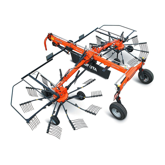
Getting to know the machine Range of This product is classified as replaceable equipment in accordance Getting to know the machine with EC directive 2006/42/EC. application The machine is a twin rotor swather, which is suitable only for the raking together of mowed stalk-type vegetation (for example, hay or straw). -
Page 23: Component Designations
Getting to know the machine Component designations Deflector bar Tine support Rotor gear Tines Transport chassis Steering Transport holder for tine supports Lifting arm Telescopic arm Tine arm shaft Main frame Attachment Sustainer Drive Swath former Deflector bar Rotor chassis carrier Tine cover stowage area... -
Page 24: Technical Specifications
Getting to know the machine Technical specifications Dimensions Transport position [m] 6.24 Length 4.10* - 4.25 Height with mounted tine supports 3.44* Height without the upper tine supports for transport position Width without the upper tine supports for transport position when using 2.89 and 2.98 tyres ... - Page 25 Getting to know the machine Dimensions Work position [m] 6.24 Length 1.50 Height in work position 7.60 - 8.40 Working width 8.50 Raking width Distance between the rotors 0.30-1.15...
- Page 26 Getting to know the machine Weights Work position [kg] Transport position [kg] Total weight 1950 Load supported on lower link 1195 Transport chassis axle load (based on load supported on lower link) Tractor equipment required Output / connections Minimum output of the tractor 40 kW (56 hp) Lighting power supply 12 V, 7-pin plug socket ISO 1724...
- Page 27 Getting to know the machine Machine equipment Swath deposit Swath former with auto-swivel Standard Rotors/tine supports/tines Number of rotors 12 swaths on the left Number of tine supports per rotor 12 swaths on the right Number of tines per tine support Removable tine arms Standard Rotor height adjustment...
-
Page 28: Pilotbox [+]
Getting to know the machine Pilotbox [+] Protect electrical parts against moisture The electronic control system, pilotbox [+] and electrical plug con- nections must be protected against damp and penetrating mois- ture. Dampness in electronic devices can lead to leakage current, which results in malfunction. - Page 29 Getting to know the machine Function The table below provides a summary of the functions. Be sure to follow the other instructions and note the safety information in the overview operating manual. Steering Machine position Function • Single-acting hydraulic control Transport •...
- Page 30 Getting to know the machine Steering Machine position Function • Pilotbox [+] is switched on. Swathing with left rotor [+] • • Switch on pilotbox [+]. Preselect position "A" on the • Preselect position "A" on the pilotbox [+]. pilotbox [+]. •...
-
Page 31: Delivery And Assembly
Delivery and assembly Checking the Delivery is in the fully assembled state Delivery and assembly The machine is delivered fully assembled. Using the checklist, check scope of delivery the loose parts on delivery. If any parts of the machine have not been fitted or are missing, please contact your dealer. -
Page 32: Checking The Length Of The Pto Shaft
Delivery and assembly Checking the The length of the PTO shaft has been selected at the factory to suit almost all types of tractor. Only in exceptional cases is a correction of length of the PTO the PTO shaft length required on individual tractors. Check the length shaft of the PTO shaft for each tractor prior to first use. - Page 33 Delivery and assembly Shortening the PTO shaft Pull the PTO shaft apart and connect one half to the tractor PTO shaft drive and one to the machine and secure them. Place the two shaft halves next to each other and: •...
-
Page 34: Checking The Steering
Delivery and assembly Checking the steering Never carry out work on the steering Steering arm Track arm Contact your dealer if specifications differ. Never carry out any work on the steering or track yourself. There is otherwise the risk of traffic Track rod accidents and accidents with fatal consequences. -
Page 35: Coupling The Machine
Coupling the machine Safety Coupling the machine Observe the safety information Observe the safety information. Disregard for safety information can lead to serious or fatal injury. See chapter »Safety«, page 6. Increased risk of injury When the machine is being coupled to the tractor, there is an increased risk of injury. -
Page 36: Coupling The Lower Link
Coupling the machine Coupling the lower link Follow the instructions for the quick-release coupling Follow the instructions below for tractors with quick-release couplings. Also note the instructions and warnings in the operating manual of the tractor manufacturer. If this requirement is ignored, the consequence may be damage to the machine and even life-threatening injuries. -
Page 37: Swivelling In The Parking Stand
Coupling the machine Swivelling in the parking stand After coupling the machine to the tractor, raise and secure the sustainer. Switch off the tractor and secure it, shut off the engine and remove the ignition key. Pull out the pins in the sustainer. ... -
Page 38: Coupling The Pto Shaft
Coupling the machine Coupling the PTO shaft When coupling the PTO shaft, make sure it is in the correct position. PTO shaft Check whether the PTO shaft must be shortened before coupling. Shorten the PTO shaft if necessary. ... -
Page 39: Wheel Chocks
Coupling the machine Wheel chocks Secure the tractor against rolling away Never remove the wheel chocks if the tractor is not otherwise secured against rolling away. Persons could be run over by the machine or the tractor. Serious or fatal injury may be caused as a result. -
Page 40: Connections
Coupling the machine Connections Electrical connections Checking the electrical cables Check the electrical cables. The electrical cables must not chafe or hang loose. Electrical cables that have been torn away or worn through must be replaced. Otherwise, damage to the machine may be caused as a result. - Page 41 Coupling the machine Hydraulic Check hoses and couplings connections Check all hydraulic hoses for damage before connecting them. Check all hydraulic couplings for firm seating after connecting them. Defective hydraulic hoses and poorly fitting hydraulic connections can trigger unanticipated movements in the machine, causing severe damage to the machine as well as personal injury.
- Page 42 Coupling the machine Connecting the Make sure the connection is correct hydraulic couplings Ensure that the hydraulic system is connected correctly, otherwise damage to the machine and personal injury will be caused as a result. Close the ball valve. ...
-
Page 43: Preparing For Use
Preparing for use Safety The following applies to all preparations for operation: Preparing for use Observe the safety information Observe the safety information. Disregard for safety information can lead to serious or fatal injury. See chapter »Safety«, page 6. Secure the machine Secure the machine against accidental starting and rolling away. -
Page 44: General
Preparing for use General The following applies when performing all adjustment work: Check the tyre pressure. Secure the machine. Lower the machine to the work position. Loosen the appropriate bolts. Make the required adjustment. Retighten the bolts. ... -
Page 45: Rotor Pitch
Preparing for use Rotor pitch The rotors are inclined transversely to the chassis. The rotor is already inclined transversely ex-factory. If the crop is not picked up cleanly, the raking quality can be improved by adjusting the rotor pitch. Optimum raking quality is achieved when the tines in the front working area and in front of the crop discharge have the lowest possible ground clearance (cf. - Page 46 Preparing for use Adjust the rotor pitch for a single axle It is possible to alter the position of the rotors lateral to the direction of travel. Release the four bolts slightly. Push the wheel carriers into the required position (see illustration on page 45).
-
Page 47: Lifting The Tines
Preparing for use Lifting the tines The time for lifting the tines can be adapted to the crop (early or late lifting). The control cam (cam disk) can be infinitely adjusted. To do this, the following steps are required. Switch off the tractor and secure it. Early ... -
Page 48: Working Depth
Preparing for use Working depth Adjust the working depth as follows: Fully lower the machine using the hydraulic control device on the tractor and advance approximately 2 metres. Switch off the tractor and secure it. Check the working depth to the ground. Sustainer Working Rotor tines... - Page 49 Preparing for use Tine saver [+] If the tines are broken, the tine saver can prevent the broken-off part from getting lost. Broken-off tine parts in the crop may damage machines that are following behind. Observe the separate assembly instructions. For a good swath deposit, both tine legs must run parallel to one another after the tine savers have been fitted.
-
Page 50: Road Transport
Road transport Safety Before transporting the machine on public roads, please read the Road transport following safety information. Compliance is mandatory and will help you to avoid accidents. Observe the safety information Observe the safety information. Disregard for safety information can lead to serious or fatal injury. -
Page 51: General
Road transport Observe transport width Observe the permissible transport widths. Put the machine in the transport position and attach lights, warning signs and protective devices. The driver and keeper of the vehicle are liable for any non-compliance with national traffic regulations. Clean lighting equipment before travelling on the road All lighting equipment must be cleaned before road transport. -
Page 52: Prior To Road Transport
Road transport Prior to road transport When driving on public roads, the machine must be in the transport position. To prepare the machine for road transport, carry out the following steps: »Setting the lowest transport height« »Folding in the deflector bar« ... - Page 53 Road transport Removing the tine Remove any crops and coarse dirt. supports Remove the 4 outer tine supports from both rotors, plug them into the transport holder and secure them (see following illustration). See »Place tine supports in transport holder«, page 54. ...
- Page 54 Road transport Place tine supports in transport holder Loosen and remove the lynch pin from the tine support. Secure the lynch pin in the rear hole of the tine support. Lynch pin Rear hole Pull off the tine support. Tine support ...
- Page 55 Road transport Fold the machine into Make sure the machine is standing level the transport Before changing from the transport to the work position (and vice position versa), make sure the machine is standing level. The machine could tip over, particularly on hillside locations. Damage to the machine and serious or fatal injury may be caused as a result.
- Page 56 Road transport Attaching the tine Exercise caution when close to unprotected tines cover Maintain a sufficiently safe distance from exposed tines. When working in the vicinity of the tines, ensure that you have a firm footing (risk of slipping on wet ground). Serious or fatal injury may be caused as a result.
-
Page 57: Road Transport
Road transport Checking the Prior to driving on the road, check the machine against the check list: machine PTO shaft drive off? Rotor in transport position? Deflector bar folded? Tine supports in transport holder and secured? ... - Page 58 Preparations on the field Safety The following applies for all preparations on the field: Preparations on the field Observe the safety information Observe the safety information. Disregard for safety information can lead to serious or fatal injury. See chapter »Safety«, page 6. Switch off the tractor and secure it Before you dismount: ...
-
Page 59: General
Preparations on the field General The following work steps are described in this section: • »Lowering the machine« • »Fitting the tine supports« • »Folding out deflector bar« • »Adjusting the swath former«... -
Page 60: Folding The Machine Into The Work Position
Preparations on the field Folding the After road transport, the machine is brought into the work position on the field. Follow the handling instructions below: machine into the work position Shutting the machine down Place the machine onto ground that is as flat as possible. ... - Page 61 Preparations on the field Lowering the machine Place the machine onto ground that is as flat as possible. Switch on the tractor. Use the single-acting hydraulic control device on the tractor to release the lifting arm locking mechanism. ...
- Page 62 Preparations on the field Remove the tine supports for both rotors from the transport holder and fit them (see illustration). See »Fitting the tine supports«, page 63. Secure the tine supports with lynch pins. Move the deflector bar to the work position until the latch engages. See »Folding out deflector bar«, page 64.
-
Page 63: Basic Settings
Preparations on the field Basic settings Fitting the tine supports Remove the tine supports from the transport holder. Attach the tine supports to the tine supports and secure with lynch Lynch pin Rear hole pin. Tine supports • The tine supports for the left rotor are labelled. - Page 64 Preparations on the field Folding out deflector After the tine supports have been attached, all protective devices must be moved from transport to work position. Latch for transport position Latch for work Fold out the deflector bar as follows: position ...
- Page 65 Preparations on the field Adjusting the swath The swath former is folded into the correct position when changing from the transport to the work position. former Adjusting the swath former in relation to the direction of travel It is possible to adjust the direction of travel of the swath former as follows: ...
-
Page 66: Operation
Operation Safety Operation Observe the safety information Observe the safety information. Disregard for safety information can lead to serious or fatal injury. See chapter »Safety«, page 6. No riding on the machine Persons or objects must never be transported on the machine. Carrying passengers on the machine is life threatening and prohibited. -
Page 67: General
Operation General The following work steps are described in this section: • »Swathing« • »Dual rotor operation« • »Single rotor operation with pilotbox [+]« • »Adjusting the swath width« • »Driving on headlands« Suitable working speeds Select a driving speed (approx. 4-12 km/h) at which the crop is picked up cleanly and completely. -
Page 68: Swathing
Operation Swathing No persons in the working area Ensure that no persons are present in the slewing and working area of the machine. Persons could be caught by the machine within this area. Fatal injury may be caused as a result. Requirements After setting the machine as described in chapter »Preparations on the field«... -
Page 69: Swath Deposit
Operation Swath deposit The following basic types of swath deposit are possible: • »Central swath with two rotors«, page 69. • »Single rotor operation with pilotbox [+]«, page 72. • »Single swath with left rotor«, page 72. • »Single swath with right rotor«, page 72. •... - Page 70 Operation Single swath with Switch off the tractor and secure it active rotor Before you dismount: Switch off the tractor. Remove the ignition key. Secure the tractor against rolling away. An unsecured tractor can run you over or trap you. Serious or fatal injury may be caused as a result.
- Page 71 Operation Single swath with right rotor in transport position The inactive side shaft is removed. See »Remove the side shaft«, page 70. Using the tractor's single-acting hydraulic control unit, raise both rotors into the transport position until the lift arms lock. ...
- Page 72 Operation Single rotor Distance from the rotor operation with Maintain a safe distance from the rotor when it is rotating. Nobody pilotbox [+] may remain in close proximity to the machine when rakes and swathers are running. Otherwise, serious or fatal injury may be caused as a result.
-
Page 73: Adjusting The Swath Width
Operation Adjusting the swath width By extending the rotors, the swath width can be adjusted to suit the crop volume and the swath type using the double-acting hydraulic control device on the tractor. For adjustment of the swath width, the machine should be in the headland position. -
Page 74: Cleaning And Care
Cleaning and care Safety The following applies to all cleaning and care work: Cleaning and care Observe the safety information Observe the safety information. Disregard for safety information can lead to serious or fatal injury. See chapter »Safety«, page 6. Secure the machine •... -
Page 75: Cleaning
Cleaning and care Cleaning Lower the machine to the work position. After each use, clean the machine of any coarse dirt and crop residue. Do not clean the bearings and piston rods of hydraulic cylinders using a high-pressure cleaner. After cleaning ... -
Page 76: Parking And Storage
Parking and storage Setting down the When setting down and parking the machine, special safety Parking and storage precautions have to be observed: machine in a secure position Observe the safety information Observe the safety information. Disregard for safety information can lead to serious or fatal injury. -
Page 77: General
Parking and storage General The machine must be uncoupled in the reverse order to that in which it was coupled. Chapter »Fold the machine into the transport position« page 55. Chapter»Coupling the machine«, section »Coupling« page 14. Uncoupling and To uncouple the machine from the tractor, proceed as follows: securing the machine ... -
Page 78: Maintenance
Maintenance For your safety The following applies to all servicing work: Maintenance Observe the safety information Observe the safety information. Disregard for safety information can lead to serious or fatal injury. See chapter »Safety«, page 6. Requirements for maintenance work Only perform the maintenance operations if you have the required expert knowledge and suitable tools. - Page 79 Maintenance Protective measures Additives in oils and lubricants may have adverse effects on health. As marking in accordance with the hazardous goods regulation is not when handling oils or necessary, please always ensure the following: lubricants Avoid skin contact Avoid skin contact with these materials. Protect your skin by means of protective skin cream or oil-resistant gloves.
-
Page 80: General
Maintenance General This information relates to general servicing work. For all servicing work, the machine must be locked in the work position. If the transport position is required for maintenance work, refer to the relevant instruc- tions for the work. ... - Page 81 Maintenance Maintenance terms Listed in this table are short explanations of the most important maintenance terms. Task Explanation Greasing Apply grease to the slide surfaces using a brush. Lubrication One or two presses of the grease gun, if not specified otherwise. Unless specified otherwise, use only plant-based oils, such as rapeseed oils.
-
Page 82: Bolt Connections
Maintenance Bolt connections Tightening screws All screws must be retightened: • After the first 5 hours of operation. • According to the frequency of use. • At least once a season. Special tightening Observe the special tightening torques for the following screw connec- tions: torques •... - Page 83 Maintenance Tightening torques All bolt connections must be tightened in accordance with the table below, if no other torques are specified. On this machine, screws with for screwed a minimum quality of “8.8” (can be seen on the screw head) are used. connections The torque specifications refer to a dry coefficient of friction (0.12).
-
Page 84: Lubrication Points For Grease
Maintenance Lubrication points for grease Working with a Before applying the grease gun grease gun clean lubricating nipples and grease gun attachment fitting. Lubricate the bearings with one or two presses of the grease gun. If you feel resistance at the second press, do not press a second time. Too much grease will force the bearings apart. -
Page 85: Lubricating The Pto Shafts
Maintenance Lubricating the The manufacturer's own operating manual is included with each PTO shaft. This includes detailed information on the relevant version of the PTO shafts PTO shaft. Check the guard components Check all guard components of the PTO shafts for wear or damage (visual inspection). -
Page 86: Lubricate Rotors
Maintenance Lubricate rotors Check the oil level with the machine horizontal only if there is visible loss of oil. Check the oil level at both rotor gears using the bleed valve. If there is a visible loss of oil, top up to the required volume. Bleed valve View from above ... -
Page 87: Filling Quantities
Maintenance Filling quantities Check the oil level with the machine horizontal only if there is visible loss of oil. Filling/drain screw Gearbox Max. oil capacity [litres] SAE 90 API-GL-4 Angular gear box (Y-transmission) Rotor gear, left Rotor gear, right Angular gear Tyres Do not drive with worn or damaged tyres Replace worn or damaged tyres immediately. -
Page 88: Hydraulics
Maintenance Hydraulics Hydraulic system at zero pressure Work must only be performed on the hydraulic system if the tractor and machine hydraulic system is at zero pressure. A pressurised hydraulic system can trigger unforeseen movements on the machine and can cause serious machine damage and personal injury. - Page 89 Maintenance Checking sliding elements The sliding elements on the two lifting arms ensure smooth and even Lock nut running of the telescopic arms. The sliding elements must be checked on a regular basis, and readjusted and the sliding surfaces lubricated if necessary.
- Page 90 Maintenance Checking the track Never carry out work on the steering Contact your dealer if specifications differ. Never carry out any work on the steering or tracking yourself. There is otherwise the risk of traffic accidents and accidents with fatal consequences. If the machine rolls at an offset angle to the tractor when driving a Steering arm straight line, the directional stability is set incorrectly.
-
Page 91: Additional Equipment
Additional equipment Additional The following additional equipment is available for this machine. All Additional equipment items of additional equipment are original parts, and are available from equipment your dealer. Additional equipment which is not part of the standard scope of delivery is indicated by a plus symbol [+] in this manual. - Page 92 Additional equipment Autan-Buffer The optional Autan-buffer provides better contour guidance and reduces the load on the lift arms. Rubber buffer Spare wheel The optional spare wheel is fitted to the deflector bar of the machine. The spare wheel can be fitted to the machine's deflector bar. Separate assembly instructions are supplied.
-
Page 93: Eliminating Faults
Eliminating faults Faults Faults can often be eliminated quickly and easily. Before contacting Eliminating faults Customer Service, refer to the table to check whether you can remedy the fault yourself. In case of a fault, proceed as follows: Immediately stop operation. ... -
Page 94: Circuit Diagrams
Circuit diagrams Hydraulic circuit Circuit diagrams diagram Left lift arm Right lift arm Swath former Lift arm extension Restrictor Restrictor 1.5 mm, 1.5 mm Restrictor Electro-hydraulic single lift 0.5 mm Tractor hydraulics... -
Page 95: Lighting Circuit Diagram
Circuit diagrams Lighting circuit diagram 2/54g 3/31 5/58R 6/54 7/58L Connecting plug 7-pin in accordance with ISO 1724 Yellow Green White Brown Black Connector and socket 7-pin in accordance with ISO 1724 Yellow Black Right indicator Right brake light Earth Left indicator Right rear light White... -
Page 96: Decommissioning
Decommissioning Environment During decommissioning, the individual parts must be disposed of Decommissioning properly and in an environmentally friendly manner. Please observe the waste disposal guidelines that are currently in force. Plastic parts Plastic parts can be disposed of in normal household waste (residual waste), depending on the laws specific to your country. -
Page 97: Ec Conformity Declaration
EC Conformity Declaration Conforms to EC Conformity Declaration EC Directive Kverneland Group Kerteminde AS 2006/42/EC Taarupstrandvej 25 DK-5300 Kerteminde Denmark declare with sole responsibility that the product SwatMaster 8442 Andex 844 9584 C and its accessories Model: VF6588 Type plate and CE marking Valid from machine number: ... - Page 98 EC Conformity Declaration...
-
Page 99: Index
Index Index Adjusting Lifting the tines Chassis Lower link Rotor pitch Coupling Single-pass swath Lubrication points Swath former General Working depth PTO shafts Cam disk Machine Care Putting away after the season Check list Setting down Headlands Uncoupling Road transport Maintenance Work position Bolt connections... - Page 100 Index Checking Single-pass swath Speed Swath deposit Dual rotor operation Swath former Adjusting the direction of travel Adjusting the height Swath width Adjusting Target group Technical specifications Dimensions in transport position Dimensions in work position Implement equipment Machine equipment Tractor equipment Weights Tightening torques Bolt connections...
Need help?
Do you have a question about the RA2584 and is the answer not in the manual?
Questions and answers