
Related Manuals for SOMNOmedics SOMNOscreen HD


Summary of Contents for SOMNOmedics SOMNOscreen HD
- Page 1 SOMNOscreen™ HD Instruction Manual Caution: Federal law restricts this device to sale by or on the order of a physician. Revision 0 November 14 , 2016...
- Page 2 SOMNOmedics GmbH Am Sonnenstuhl 63 – 97236 Randersacker – Germany Phone: (+49) 931 / 35 90 94 - 0 – Fax: (+49) 931 / 35 90 94 - 49 All proper names marked with TM are copyright protected by SOMNOmedics.
-
Page 3: Table Of Contents
Content Getting started – Quick Guide ..................5 Introduction ........................7 Intended use/Indication of Use................. 7 Patients ........................8 About this instruction manual ................... 8 Explanations of Symbols used in this Manual ............8 Safety instructions ....................8 System components & accessories ............... 12 Label / symbols ...................... - Page 4 Reviewing the raw data ................... 36 Zoom ......................36 Impedance display ..................36 Warnings on the display ..................3637 The docking station ....................38 Data transfer via docking station ..............38 Recharging the battery ..................38 Firmware Update .................... 38 Troubleshooting ......................
-
Page 5: Getting Started - Quick Guide
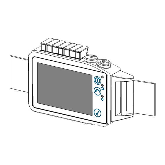
Getting started – Quick Guide Control and display elements of the main device Control functions Control functions which are active and selectable are backlit. Power button: when touching the power button (1) the device can be switched on and off respectively, or, during the measurement, the display can be switched on. The button flashes red when recording or green when the device is in waiting mode. - Page 6 2 Wait for the unlock screen to appear then move the slider form left to right...
-
Page 7: Introduction
Introduction The SOMNOmedics team would like to thank you for purchasing this product. We are confident that you will enjoy using the SOMNOscreen™ HD for many years. The SOMNOscreen™ HD has been developed by SOMNOmedics to meet the highest quality control standards available. -
Page 8: Patients
Damaged parts must be replaced immediately. Please contact SOMNOmedics or your SOMNOmedics Distributor. If the device is damaged (e.g. broken case) it has to be taken out of service. If any sensor cable or the device housing itself is damaged, a low risk of injury to the patient may occur through a direct connection to the ground lead. - Page 9 Prevent the device of rain. Should any liquids enter the device, the device must be cleaned immediately by SOMNOmedics customer service personnel. Following this, the device will undergo a safety- related examination. Do not switch on the device if any liquids have entered.
- Page 10 (mobile) phones, CB radio devices, microwave ovens etc. where the electrical field may exceed 10 V/m (according to norm IEC 60601-1-2). If a battery change is required, only batteries specified by SOMNOmedics may be used. SOMNOmedics cannot guarantee error-free operation if different batteries are used.
- Page 11 Opening the case, repairing or modifying the SOMNOscreen™ HD in any way will void the guarantee and might affect the safety of the device. Only SOMNOmedics and its authorised distributors may repair the unit.
-
Page 12: System Components & Accessories
System components & accessories Main device Internal channels: body position, movement, flow/snore, CPAP-pressure, RIP effort abdomen, ambient light, patient marker, battery status Additional Sensors PSG headbox EEG/EOG combi electrode 1-Channel ECG RIP effort sensor thorax Multiplex-RIP effort sensor (for paediatric use) SpO2 sensor (SpO2, pulse, pleth), paediatric or adult Limb EMG sensors left and/or right Microphone... -
Page 13: Label / Symbols
Label / symbols Information, Symbols, Icons and Classifications on the Type Label Manufacturer information / address Direct Current Read the instruction manual very carefully before you start working with the SOMNOscreen™ HD. Protection Class: BF The CE icon shows that the SOMNOscreen™ HD complies with the applicable regulations of the EU and that the conformity was declared by the manufacturer. - Page 14 Symbols on the Docking Station IP20 This device complies with the IP-Protection-Class “20”. Electronic waste – no domestic garbage USB Interface Device Type Manufacturer information / address The CE icon shows that the SOMNOscreen™ HD complies with the applicable regulations of the EU and that the conformity was declared by the manufacturer.
-
Page 15: Preparing The Patient: Applying Main Device, Sensors And Electrodes
Preparing the patient: applying main device, sensors and electrodes Note: The main device should be placed on top of light clothes (nightshirt, pyjamas) and should not be in direct contact with the skin. Note: Attach the belts and sensor/electrode wires securely to the patient to avoid strangulation. Fix the sensor cable with adhesive tape if needed. - Page 16 For home sleep tests it is highly recommended that the physician/medical professional either attach the device and the accessories before the patient leaves the office or the physician explain and demonstrate the attachment and use of the device and sensors face-to-face. The physician/medical professional should go through the following points with the patient: 1.
-
Page 17: Connecting The Sensor Plug To The Main Device
Connecting the sensor plug to the main device Please insert the sensor plugs into the main device as shown in the following image: Inserting a sensor plug into the main device The device automatically recognizes the connected sensors. Main device with plugged-in sensors; signals are shown on the display The luer-lock plug of the nasal cannula is screwed directly into the sensor port. - Page 18 Connecting the luer-lock plug to the moisture retention filter and then to the main device.Insert the headbox plug into the designated port and position. Turn the safety screw as indicated by the arrows in the image and indicated on the plug/device. Connecting the headbox plug to the main device Insert the SpO2 plug into the bottom as shown in the image.
-
Page 19: Attaching The Effort Belts
Note: In order to prevent damage of the sensor, patient should take off SpO2 sensor while washing hands or splashing water. Attaching the effort belts The effort belts are provided in different size. Measure the patients circumference for selecting the correct size. Insert the thin end of the effort belt into the slot on the left side of the main device (seen from the front). -
Page 20: Nasal Cannula
Attaching the effort belts to the patient Nasal cannula Attach the nasal cannula to the patient’s nose. Make sure that the holes of the sensor elements (highlighted red in the following image) are placed directly below the nostrils. Note: Nasal cannulas are single-use items. Adjust fixing sleeve in order to secure the sensor’s position. -
Page 21: Spo2 Sensor
Attaching the PLM electrodes to the legs Note: Do not use dried-out adhesive snap electrodes. Only use electrodes provided by SOMNOmedics to ensure the best signal quality. Note: When using the leg EMG sensors, always use a ground lead electrode to ensure optimal signal quality. -
Page 22: Microphone
Microphone Attach the microphone between the larynx and carotid artery to record the snoring sounds. (DO NOT place the sensor directly on the larynx and not too close to the carotid artery). Ensure that the cable does not restrict the patient’s breathing or endanger the patient in any way. Attach the sensor with the flat side of the microphone towards the skin. -
Page 23: Cpap Sensor And Cpap Device
Adjust fixing jacket in order to secure the sensor’s position. Attaching the thermistor Adapter for thermistor and nasal cannula CPAP sensor and CPAP device There are two ways to connect the CPAP sensor to the CPAP device: If the CPAP mask does not have a port for a pressure tube: Place an oxygen adapter (sold separately) between the angled piece of the mask and the oxygen hose. -
Page 24: Ecg
If the CPAP mask has a port for a pressure tube: Connect the supplied silicone pressure tube to the port on the CPAP mask. Now, connect the other end of the tube to the port of the pressure sensor on the main device. Option B: Connecting the pressure sensor directly to the mask Attach the red electrode to a disposable snap electrode and attach it to the patient at ICR 4. -
Page 25: Eeg/Eog
1-channel ECG sensor Attaching the 1-channel ECG sensor EEG/EOG Attaching the PSG headbox according to AASM Guidelines Positions of the electrodes (PSG according to AASM) GND: Centre of forehead REF: Applied to Cz, see 10/20 system EOG l: 1cm above outer canthus of left eye EOG r: 1cm below outer canthus of right eye F3/4: See 10/20-System C3/4: See 10/20-System... - Page 26 Application for 32-channel headbox according to 10-20 System Preauricular point right inion left Electrode positions (10-20) Plug the EEG electrodes in according to the labelling and colour coding of the headbox. Use the same kind of electrodes everywhere (e.g. only Ag/AgCl or only gold cup).
-
Page 27: Operating The Main Device
Operating the main device The control and display elements Control and display elements of the main device Control functions Control functions which are active and selectable are backlit. Power button: when touching the power button (1) the device can be switched on and off respectively, also, the display can be turned on during the measurement. -
Page 28: Switch-On /-Off Of The Device
Switch-on /-off of the device Switch-on Place your finger on the power button (1) and follow the instructions on the screen. Display unlock screen Switch-off Place your finger on the power button (1). The device starts to shut down: Display turning off When the device is ready to be switched off you see the following screen: Display confirm shutdown Confirm the notification by touching the confirm button (3) or the check mark on the screen. -
Page 29: Navigation In The Menu
Domino. Press “Start” to begin a measurement directly on the device. You will then be guided through the menu. SOMNOmedics Tapping on the SOMNOmedics logo will display the Logo device name (serial number), the installed firmware version and SOMNOmedics contact details. - Page 30 Signal display on/off – Tap on the button to activate or deactivate this function. “Signals on”: raw data and measurement parameters are shown during the measurement. “Signals off”: no signals are displayed during the measurement. Use this function if you do not want the patients to see their pulse rate, etc.
-
Page 31: Bluetooth On/Off
Stop signal If less time is needed for the signal check than originally check estimated, you can end the signal check with this button. The device returns to wait mode. Signal view during recording Patient marker Tap on this symbol to set a patient marker. A menu opens where the relevant marker can be defined. -
Page 32: Initialization Of A Measurement
Initialization of a measurement A measurement can be initialized via the DOMINO software or directly at the device. Initialization via DOMINO software When initializing a measurement via the DOMINO software you can enter the patient’s name, ID and further information such as date of birth, height and weight. This data is saved together with the measurement. - Page 33 Virtual docking station, main device connected Click on “Initialise” to enter the patient data etc. (alternatively use icon 1 of the DOMINO panel). After successful initialization the status is displayed (patient data, start, montage). You can change the initialization by clicking “change”. The initialization dialogue will re-open. Please see further information about the initialization process in the DOMINO software instruction manual.
-
Page 34: Initialization Via The Device
Initialization via the device As an alternative to the above, you can start a measurement directly on the device. When Bluetooth is active, the data can be displayed in an online recording or with the SOMNOmedics app on a tablet. -
Page 35: Signal View On The Display
If you select a “new” montage, a new montage will be generated based on what sensors are connected during the signal check. Signal view on the display Before and during the measurement you can see the recorded data on the display. Tap on a sensor icon to see the corresponding raw data. -
Page 36: Scrolling Channels
SpO2 sensor (saturation, pulse, pleth) PSG headbox (EOGs, EEGs, EMGs) First the impedance head appears and thereafter the signals are displayed Scrolling channels Swipe vertically ↕ on the display to see further channels of the same signature group. See individual channels In the raw data view, tap on the channel you would like to see separately. - Page 37 transfer the measurement. If you wish to delete the measurement, confirm with “yes”. The sensor(s) are/ is not part of the Plugged-in sensors are not part of the montage. Do you want to add them to the montage. They can be added. The montage montage? will be updated.
-
Page 38: The Docking Station
The docking station Make sure that the docking station is connected to the power supply system via the power plug and to the PC via USB cable. The upper LED displays that the docking station is connected to the power. The lower LED displays yellow if the inserted battery is charging and green if it is fully charged. -
Page 39: Troubleshooting
Troubleshooting Logbook Code Description Short description in Further actions at the logbook device Measurement was finished as Terminated correctly scheduled Measurement was stopped Stopped, low batt. due to low battery voltage. Online measurement Online stopped by PC finished in DOMINO. The device switches off by itself. -
Page 40: Cleaning And Maintenance
Wipe the case of the main device with a lint-free, soft cloth slightly moistened with a mild detergent. We recommend Terralin Liquid for cleaning. Note: This SOMNOmedics device complies with protection class IP 22 regarding ingression of humidity and water. Cleaning should be performed with a lint-free and damp cloth. -
Page 41: Maintenance Interval
Maintenance interval After 3 years of use, send the main device to SOMNOmedics for validation and inspection. The inspection includes an examination for damage, a function test and a firmware update. Usage and maintenance of the rechargeable battery An accumulator is a rechargeable battery. -
Page 42: Technical Data
Technical data Component Sensor Resolution Measurement range Frequency range Accuracy Measurements and weight 0.07 – 15 Hz Thermistor 16 Bit 115 x 78 x 25 mm 190 g incl. battery 0.5 – 10 Hz Activity external 16 Bit ± 1 g ±... - Page 43 Storage medium Industrial Grade µSD card, 1 GB in standard version Temperature range storage 0 – 50 °C, In use: -20 – 70 °C Only use memory cards authorised by SOMNOmedics While in use: 10 – 90 %, non-condensing Humidity When stored/transported: 10 –...
-
Page 44: Service
Service Interference If safe and proper operation is no longer possible, the device must be put from operation and securely stored to prevent inadvertent operation. This applies: - If the device is visibly damaged (broken housing). - If the device is no longer functional (incorrect measurement results). - If parts of the device are loose. -
Page 45: Warranty
The warranty only refers to the main device SOMNOscreen™ HD and includes a period of 24 months. Note: If you use accessories which are not authorized by SOMNOmedics and it comes to service provision, this will be invoiced. Note: It is not permitted to open the device. Repairs, opening the device and modifications are carried out exclusively in the factory. - Page 46 The use of accessories, sensors, and cables other than those provided by SOMNOmedics America Inc. GmbH may result in increased emission and/or decrease immunity of this device.
- Page 47 Harmonic emissions, Class A connected to the public low-voltage power supply network IEC 61000-3-2 (*) that supplies buildings used for domestic purposes. Voltage fluctuation/flicker Complies emissions, IEC 61000-3-3 (*) (*) Note: For devices with a power consumption between 75 W and 1000 W only. Guidance and manufacturer’s declaration —...
- Page 48 Guidance and manufacturer’s declaration — electromagnetic immunity The equipment is intended for use in the electromagnetic environment specified below. The customer or the user of the equipment should assure that it is used in such an environment. Electromagnetic environment – Immunity test IEC 60601- test level Compliance level...
-
Page 49: Accessories
Accessories Please request our latest catalogue from your local Distributor or contact SOMNOmedics. APPLICATION PARTS (*), SENSORS, ACCESSORY SOMNOscr een HD single-use Article name Art.-No. included (one sleep session) ● SOMNOscreen HD basic device NGD050 ● SSC030 ● Docking station (incl. power supply and USB-cable) NGA102 ●... -
Page 50: Service Hotline Und Contact
Send us a message by fax at any time. +49 (0) 9 31 / 35 90 94 49 Send us your query by email any time. service@somnomedics.de Get free access to current software updates via service login on our website www.somnomedics-diagnostics.com.
Need help?
Do you have a question about the SOMNOscreen HD and is the answer not in the manual?
Questions and answers