
Related Manuals for SOMNOmedics SOMNOtouch PSG


Summary of Contents for SOMNOmedics SOMNOtouch PSG
- Page 1 NSTRUCTION MANUAL SOMNOtouch™ PSG SOMNOmedics America Inc. – 815 Ponce de Leon Blvd., Suite P-209 – Coral Gables, FL 33134 Toll free: 866 361 9937 info@somnomedics-diagnostics.com www.somnomedics-diagnostics.com...
- Page 2 SOMNOmedics America Inc. – 815 Ponce de Leon Blvd., Suite P-209 – Coral Gables, FL 33134 Toll free: 866 361 9937 info@somnomedics-diagnostics.com www.somnomedics-diagnostics.com Rev. 0 01.04.2019 All proper names marked with TM are copyright protected by SOMNOmedics.
-
Page 3: Table Of Contents
Content Introduction ............................ 4 Intended Use ..........................4 Patients ............................4 About SOMNOtouch™ PSG ......................5 Model and Device number ......................5 Elements of keyboard ......................... 6 Safety instruction ........................... 7 Operation ............................9 Preparing a new measurement ....................9 Application of the sensors ...................... -
Page 4: Introduction
1 Introduction The SOMNOmedics team would like to thank you for purchasing this product. We are confident that you will enjoy using the SOMNOtouch™ PSG for many years. The SOMNOtouch™ has been developed by SOMNOmedics to meet the highest quality control standards available. -
Page 5: About Somnotouch™ Psg
2 About SOMNOtouch™ PSG Internal buzzer Internal buzzer, body position sensor On/ Off Button + acceleration sensor (x, y, z direction) Internal Effort Sensor Patient marker SpO2 sensor connection Pressure sensor connection External Signal- input (AUX) SpO2 Sensor connection Interface/ Charging port External Signal- Pressure sensor connection... -
Page 6: Elements Of Keyboard
Label of the SOMNOtouch™ - Notes, symbols and classification HF-Transmitter with integrated Bluetooth Protocol. Read the instruction manual very carefully before you start working with the device Protection Class: BF The CE icon shows that the device complies with the applicable regulations of the EU and that the conformity was declared by the manufacturer. -
Page 7: Safety Instruction
When this LED is Yellow, the battery is being charged Status LED 2 When this LED gets off, the battery is fully charged Charging When this LED is off, no charge is taking place. The patient uses the button as a Marker during the measurement. - Page 8 Systems, Cellular Phones, Microwave Ovens, etc. within a distance of 30 cm (in accordance with IEC 60601-1-2) to device.. Only sensors designed and supplied by SOMNOmedics may be used with this unit. All sensors are provided unsterile and should never be sterilized.
-
Page 9: Operation
Opening the case, repairing or modifying the SOMNOtouch™ in any way will void the guarantee and might affect the safety of the device. Only SOMNOmedics and its authorised distributors may repair the unit. Never charge the internal battery with a docking station other than the one supplied by SOMNOmedics, otherwise the battery may be damaged. - Page 10 Abb. 4 ‘Preparing new recording’ window: ‘Date’ tab Activate the ‘Manual Start’ checkbox, enter the intended recording duration and select ‘Next’ or the ‘Montage’ tab. The DOMINO software contains assemblies for all EEG options. If you need other sensors, you can adapt the montage.
-
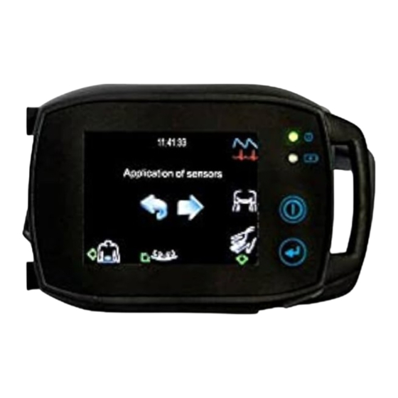
Page 11: Application Of The Sensors
Application of the sensors The main device should be placed on top of light clothes (nightshirt, pyjamas) and should not be in direct contact with the skin. Note: Carefully attach straps and sensor cables to the patient to prevent strangulation. If necessary, additionally secure the sensor cables with adhesive strips. - Page 12 Abb. 9 Threading the Effort Belt Abb. 10 Attaching the effort belt to the abdomen Clean the skin areas to which you attach the PLM electrodes with alcohol pads. Connect the PLM electrodes (e.g. SEN012) to the push-button electrodes of your sensor.
- Page 13 Put the nasal cannula on the patient. Make sure that the sensor element openings colored red in the following illustration are in the nostrils. Then, connected the nasal cannular together with the filter (screwed onto the other end of the nasal cannula) to the LuerLock connector of the SOMNOtouch Abb.
- Page 14 Abb. 16 AASM-Headbox 3) 6-chanal-EEG module Abb. 17 Application plan for 6-chanal-EEG-module. Plug the electrode cables according to the application plan into the EXG-Headbox: Abb. 18 EXG-Headbox for 6-chanal-EEG-Module with ECG. 4) Application of the Headbox The headbox can be fastened to the thoracic belt or an (optional) shoulder belt with the clip at its back. To fasten the headbox at the thorax, the opening of the clip has to point downwards (Abb.
-
Page 15: Starting A New Case Online
To fasten the headbox to the shoulder belt, the opening of the clip has to point to the left (Abb. 19, right). Note: To turn the clip please remove the screws, turn the clip for 90° to the right and tighten the screws again. - Page 16 Abb. 22 Online Mode: ‘Montage’ tab" Lists the available montages Shows the type of device for which the selected montage was prepared (Please note: The device type of the montage and that of your hardware must be the same.) Lists any previously created analysis templates or analysis- / raw data profiles linked to the selected montage Shows the sensor application on a virtual patient Online-Mode needs to be activated.
- Page 17 Abb. 23 Online Mode: ‘Recording’ tab Set the recording duration Shows the maximum online recording time depending on the capacity of the hard disk Program an online recording with ‘Auto Start’ if desired and/or the optional ‘Signal Check’ (Please note: an online connection will need to be established to activate this feature, see 10) Comments can be entered if necessary Activate the video recording...
- Page 18 Confirm with „OK“ . PSG the following window appears in which ‘Connect to running record’ need For the SOMNOtouch to be selected. Abb. 24 Start online recording for SOMNOtouch Please note: The device has already started recording, but the data is not yet stored on the computer. Start the online recording by selecting the "Start recording"...
-
Page 19: Starting Der Somnotouch
Digital zoom The zoomed view will be saved only. This is why the software will swap back to the not zoomed view automatically after a few seconds. Stop video recording Stops recording the video on the hard disk drive. You can still watch the patient on the monitor. - Page 20 Abb. 28 Information “Non-transferred measurement” Otherwise, after you have pressed the "Start" button, an information window will appear (Abb. 29) with the details of the patient's name, the selected assembly, body size, start time and duration. Check that this matches the data initialized on the PC. For a “Manual Start”...
-
Page 21: Display During Recording
Abb. 31 Signal control before measurement Tap on a single signal channel in the left to middle part of the display to see it in detail. To change the time range press on the time basis at the bottom left. Abb. - Page 22 Abb. 34 Settings during recording With deactivated display the settings for Bluetooth and sounds can only be adjusted previous to the recording in the settings menu. The blinking of the LED can only be set during the PC-initialization. If you click on the trace button (6) you open the signal control. There you can see the signals of the sensors and you can check on their quality.
- Page 23 Abb. 37 Selection of Patient Marker Frequent activation of the display may result in the battery not being sufficient for the selected measurement time. To prevent this, the display is deactivated. In this case a note appears on the display, telling you that the battery is low and the display will be deactivated for the recording to continue.
-
Page 24: Settings Of The Somnotouch Tm
Settings of the SOMNOtouch To change the settings, e.g. language, tap on the gearwheel symbol at the start display. Abb. 38 Start-Display of SOMNOtouch All settings which can be changed manually on the device will appear. Abb. 39 Settings 1) Bluetooth The Bluetooth function must be permanently activated. - Page 25 Key Sound Warning Sound Abb. 41 Sound settings 3) Display In the display menu you can change the brightness of the display and the background colour for the menus. During the recording the background is black. Abb. 42 Display settings The display during the recording can be de-/activated during the start preparations.
-
Page 26: Manual Abortion Of The Recording
(On / Off Button + Patient marker) or delete a measurement on the device. The device-specific code is the four-digit serial number of the device, e.g. SOMNOtouch PSG serial number 0123 has the code 0123. -
Page 27: Troubleshooting
PC. 6 Maintenance Maintenance rate Return the SOMNOtouch™ to SOMNOmedics after 3 years of usage for inspection. The inspection includes calibration of all recording channels and visual inspection for any external damage. Cleaning and disinfection Clean the equipment regularly to ensure trouble-free operation. -
Page 28: Use And Maintenance Of The Rechargeable Battery
Note: Never recharge the battery using a different docking station than the one provided by SOMNOmedics (TOS902) as the battery could be damaged. Functional Testing of the integrated Pulse Oximeter Functional testers for pulse oximeters cannot be used for verification of the accuracy of the integrated pulse oximeter or it’s sensors. -
Page 29: Service
7 Service Technical specification Name Measuring Frequency Range Accuracy Range Basic device 3x Acceleration Sensor (x,y ± 6 g ± 10 % &z direction) Body Position Right, left, supine, prone, upright Pulse Rate 30 - 240 bpm ± 3 bpm Marker Button 70 - 100 % ±... -
Page 30: Advice On The Electromagnetic Compatibility
The use of accessories, sensors, and cables other than those provided by SOMNOmedics GmbH may result in increased emission and/or decrease immunity of this device. - Page 31 2,4,6 kV contact 2,4,6 kV contact Electrostatic discharge Floors should be wood, (ESD), IEC61000-4-2 concrete or ceramic tile. If floors 2,4,8 kV air 2,4,8 kV air are covered with synthetic material, the relative humidity should be at least 30 %. 2 kV for power supply 2 kV for power supply Electrical fast...
-
Page 32: Interference
The device is used according to the instruction manual and all safety instructions are followed. The Warranty claim only refers to the SOMNOtouch™ unit and covers a warranty period of 24 months. Note: If you use accessories which are not authorised by SOMNOmedics and it comes to service provision, this will be invoiced. -
Page 33: Accessories And Spare Parts
Accessories and Spare Parts Please request our latest catalogue from your local Distributor or contact SOMNOmedics. Firmware Update When the DOMINO software is updated, an update of the firmware may be required. This update will be carried out automatically after accepting the notification. It is necessary for the SOMNOtouch device to be put into the docking station and left there until the update is fully completed. -
Page 34: Contact
Send us a message by fax at any time. +49 (0) 9 31 / 35 90 94 49 Send us your query by email any time. service@somnomedics.de Get free access to current software updates via service login on our website www.somnomedics-diagnostics.com. -
Page 35: Notes
Notes -35-...
Need help?
Do you have a question about the SOMNOtouch PSG and is the answer not in the manual?
Questions and answers