Moxa Technologies MGate 5102-PBM-PN Quick Installation Manual
Hide thumbs
Also See for MGate 5102-PBM-PN:
- Quick installation manual (6 pages) ,
- User manual (60 pages) ,
- Quick installation manual (2 pages)
Table of Contents
Advertisement
Quick Links
MGate 5102-PBM-PN
Quick Installation Guide
Moxa Americas:
Toll-free: 1-888-669-2872
Tel:
1-714-528-6777
Fax:
1-714-528-6778
Moxa Europe:
Tel:
+49-89-3 70 03 99-0
Fax:
+49-89-3 70 03 99-99
Moxa India:
Tel:
+91-80-4172-9088
Fax:
+91-80-4132-1045
Version 3.1, November 2019
Technical Support Contact Information
www.moxa.com/support
2019 Moxa Inc. All rights reserved.
Moxa China (Shanghai office):
Toll-free: 800-820-5036
Tel:
+86-21-5258-9955
Fax:
+86-21-5258-5505
Moxa Asia-Pacific:
Tel:
+886-2-8919-1230
Fax:
+886-2-8919-1231
P/N: 1802051020013
*1802051020013*
Advertisement
Table of Contents

Subscribe to Our Youtube Channel
Related Manuals for Moxa Technologies MGate 5102-PBM-PN


Summary of Contents for Moxa Technologies MGate 5102-PBM-PN
- Page 1 MGate 5102-PBM-PN Quick Installation Guide Version 3.1, November 2019 Technical Support Contact Information www.moxa.com/support Moxa Americas: Moxa China (Shanghai office): Toll-free: 1-888-669-2872 Toll-free: 800-820-5036 Tel: 1-714-528-6777 Tel: +86-21-5258-9955 Fax: 1-714-528-6778 Fax: +86-21-5258-5505 Moxa Europe: Moxa Asia-Pacific: Tel: +49-89-3 70 03 99-0...
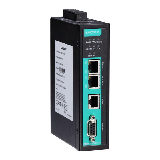
- Page 2 Overview The MGate 5102-PBM-PN is an industrial Ethernet gateway for PROFIBUS-to-PROFINET network communication. Package Checklist Before installing the MGate 5102-PBM-PN, verify that the package contains the following items: • 1 MGate 5102-PBM-PN gateway • RJ45 to DB9 cable (for console use) •...
- Page 3 3. Connect the unit to the PROFINET I/O controller. 4. The MGate 5102-PBM-PN is designed to be attached to a DIN rail or mounted on a wall. For DIN-rail mounting, push down the spring and properly attach it to the DIN rail until it “snaps” into place. For wall mounting, install the wall-mount kit (optional) first and then screw the device onto the wall.
- Page 4 Wall or Cabinet Mounting Two metal plates are provided for mounting the unit on a wall or inside a cabinet. Attach the plates to the unit’s rear panel with screws. With the plates attached, use screws to mount the unit on a wall. The heads of the screws should be 5 to7 mm in diameter, the shafts should be 3 to 4 mm in diameter, and the length of the screws should be...
- Page 5 Power Input and Relay Output Pinouts Shielded Power Power N.O. Common N.C. Power Power Ground Input 2 Input 2 Input 1 Input 1 Specifications Power Input 12 to 48 VDC Power Consumption 12 to 48 VDC, 430 mA (max.) (Input Rating) Operating Temperature Standard Models: 0 to 60°C (32 to 140°F) Wide Temp.
- Page 6 ATTENTION For installations in hazardous locations (Class 1, Division 2): These devices are to be installed in an enclosure with a tool-removable cover or door, suitable for the environment. NOTE This equipment is suitable for use in Class 1, Division 2, Groups A, B, C, D, or nonhazardous locations only.
Need help?
Do you have a question about the MGate 5102-PBM-PN and is the answer not in the manual?
Questions and answers