Table of Contents
Advertisement
Advertisement
Table of Contents
Troubleshooting

Subscribe to Our Youtube Channel
Related Manuals for Bil-Jax ESP 19


Summary of Contents for Bil-Jax ESP 19
- Page 2 Repair or replace all damaged or malfunctioning components. Bil-Jax, Inc. is dedicated to the continuous improvement of this and all Bil-Jax products. Therefore, equipment information is subject to change without notice. Direct...
- Page 3 TABLE OF CONTENTS TABLE OF CONTENTS ILLUSTRATIONS AND TABLES 1 SAFETY LEGEND: SAFETY ADVISORIES BEFORE OPERATION DURING OPERATION MAINTENANCE SAFETY BATTERY MAINTENANCE DAMAGED EQUIPMENT POLICY 2 INTRODUCTION SPECIFICATIONS WARRANTY 3 OPERATION OPERATOR CONTROLS NORMAL OPERATING PROCEDURE EMERGENCY LOWERING PROCEDURE LIFT VEHICLE TRANSPORT 4 MAINTENANCE SCHEDULED SERVICE CHECKS UNDERGUARD SERVICE CHECK...
- Page 4 TABLES AND ILLUSTRATIONS Table 1-1 Minimum Safe Approach Distances Table 2-1 Specifications Figure 3-1 Lower Control Box Figure 3-2 Upper Control Box Figure 3-3 Battery On/Off Switch Figure 3-4 Emergency Lowering Valve Figure 3-5 Lifting and Tow Procedures Figure 3-6 Travel Brake and Steering Linkage Table 4-1 Daily/Weekly Service Checks...
- Page 5 SAFETY Proper training is required for the safe operation of any mechanical device. Failure to follow all instructions and safety precautions in this manual and attached to the lift will result in death or personal injury. Prior to Operation: Read, understand and obey all instructions and safety precautions in this manual and attached to the lift.
- Page 6 LEGEND: SAFETY ADVISORIES The following safety advisories are used throughout this manual to indicate specific hazards when operating or maintaining the machine. Read, understand and obey all safety advisories to prevent improper service, damage to equipment, personal injury or death. DANGER Warns of operation near electrical power sources that could lead to personal injury or...
- Page 7 BEFORE OPERATION DURING OPERATION Read and observe the following general safety Ensure the following general safety precautions are precautions before operating the ESP 19. followed while operating the ESP 19: ALWAYS survey the usage area for potential DANGER hazards such as untampered earth fills, unlevel...
- Page 8 ALWAYS cordon off area around the base to keep personnel and other equipment away from it while in use. ALWAYS stay clear of wires, cables, and other overhead obstructions. ALWAYS disconnect power at the batteries when not in use to guard against unauthorized use. NEVER allow electrode contact with any part of the platform if welding is being performed from the platform.
- Page 9 Battery Maintenance Read and observe the following general safety precautions when performing battery maintenance on the ESP 19. Check battery charge indicator for proper state of charge on maintenance free batteries before using lift. ALWAYS wear safety glasses when working near battery.
- Page 10 Bil-Jax Service Department at 800-537-0540. Damage Repair Notice There may be occasions when a Bil-Jax lift is involved in an incident resulting in non- structural damage. When this occurs and repairs are made by the owner or area distributor, please notify Bil-Jax of these non-maintenance repairs and request a repair form to be filled out and returned to Bil-Jax.
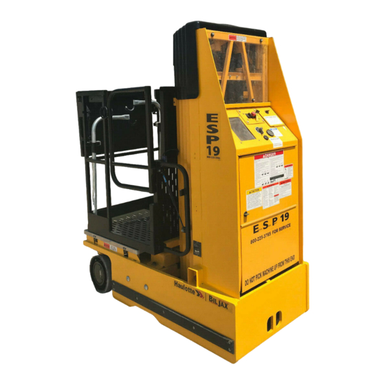
- Page 11 INTRODUCTION The ESP 19 hydraulic lift is designed and manufactured for use as a warehouse stocking and order picking vehicle. Its guard rail design permits the operator to ride on the platform with the load, while transferring parts to and from multiple overhead storage locations.
- Page 12 A list of those components and their warranties is available upon written request to Bil-Jax. Bil-Jax shall not in any event be liable for the cost of any special, indirect, or consequential damages to anyone, product, or thing. This warranty is in lieu of all other warranties expressed or implied.
- Page 13 OPERATION OPERATOR CONTROLS Most of the operator controls for the ESP 19 are located on the upper and lower control boxes. Other operator controls include the BATTERY ON/OFF switch and the emergency lowering valve. The BATTERY ON/OFF switch, located on the left side of the lift base, is the main power disconnect switch for the lift vehicle.
- Page 14 Upper Control Box The upper control box, Figure 3-2, is in the lift cage. The upper control box enables lift and travel operations whenever the BATTERY ON/OFF switch is in the ON position and the lower control box key switch is in the UPPER CONTROL position.
- Page 15 NORMAL OPERATING PROCEDURE Perform the following procedures to operate the sounds an alarm beeper. Once the platform is ESP 19 platform lift vehicle. lowered, floor travel is again enabled to allow travel to a level area. Read and follow all safety precautions contained in Section 1 and all responsibilities outlined in the ANSI A92.3 reprint in Section 7 of this manual.
- Page 16 EMERGENCY LOWERING PROCEDURE In an emergency, a person at floor level can lower the platform by holding the UPPER CONTROL/OFF/LOWER CONTROL key switch in the LOWER CONTROL position and turning the UP/DOWN selector switch to the DOWN position. (If the upper control box emergency stop pushbutton is depressed, the platform will not lower.) An emergency lowering valve is shown in Figure 3-4.
- Page 17 The forks of a lift truck (2-ton minimum capacity) can be used to raise the ESP 19 for loading onto a trailer or for blocking up the lift vehicle for maintenance. Forks must be inserted a minimum of 32 inches before raising the ESP 19.
- Page 19 MAINTENANCE SCHEDULED SERVICE CHECKS Daily/Weekly Service Checks Perform the daily and weekly service checks listed in Table 4-1. Table 4-1. Daily/Weekly Service Checks Daily Service Check before use Weekly Check that all upper and lower control box controls work properly. Check for hydraulic oil leaks.
- Page 20 6 Month/Yearly Service Checks Perform the service checks in Table 4-2 every 6 months or every 12 months, as indicated. Table 4-2. 6 Month/Yearly Service Checks Every Every Service Check 6 months 12 months Check chain assemblies for split leaves, loose pins, excessive wear, or elongation.
- Page 21 UNDERGUARD SERVICE CHECK The underguard is a safety device located under the cage/platform that shuts down operation of the lift when weight is applied. Perform the following procedure weekly to verify the underguard is working properly. Turn power to lift ON and raise cage/platform using the lower control box a minimum of 3 feet above the underguard.
- Page 22 Lubrication makes operation of the ESP 19 more efficient and extends the life of the lift vehicle. Perform the following lubrication procedures. Lubricate lift chains with clean 40-weight oil. Refer to Figure 4-2. Figure 4-4. Rear Casters Lubrication See Figure 4-4. Grease rear caster axles and...
- Page 23 HYDRAULIC SYSTEM Hydraulic system maintenance varies by the amount Perform the following procedure to bleed trapped air of use and the environment in which the lift vehicle is from the hydraulic system. used. Keeping the hydraulic oil clean and the Fill the reservoir to the MAXIMUM level with the reservoir properly filled will help prevent possible proper hydraulic fluid.
- Page 24 Perform the following procedure to adjust the WARNING pressure relief valve. Refer to Figure 4-6. Closely read and adhere to the following Move the ESP 19 lift platform to the fully DOWN instructions whenever you remove and install position. the flow restrictor valve. Failure to properly Center 450 pounds of weight on the lift platform.
- Page 25 Valve Operation Refer to Figure 4-8 for valve locations and the hydraulic diagram in Figure 4-15. The valves are labeled on the valve manifold as A, B, C, FA and FB. The platform down valve is located at the base of the lift cylinder.
- Page 26 Slide piston rod (6) with wear ring (7) into cylinder jacket (2). Hydraulic cylinder removal requires extensive disassembly of the ESP 19 lift vehicle. Contact Lubricate o-ring (3), packing ring (4), and rod Bil-Jax for assistance before removing the wiper (5) with clean hydraulic oil or petrolatum.
- Page 27 ELECTRICAL SYSTEM Regular maintenance is necessary to keep the When there is power to the battery charger, a electrical system in proper working order. Check red “ON-CHARGING” LED on the charger will daily all electrical wires for cuts, broken wires, be lit and the ammeter will display the rate of potential short circuits, and any other damage.
- Page 28 LIFT CHAINS AND SLIDE BLOCKS After making a lift chain adjustment, verify that at WARNING least 1/8 in. (3 mm) of the threaded clevis rod extends beyond the lock nut. Also recheck the Do not operate a unit on which any chain slack of all lift chains at mid-span;...
- Page 29 Slide Block Adjustment Annually check for wear on the slide blocks and without hesitation or stopping, the blocks are replace or retighten as necessary. If the lift exhibits properly adjusted. excessive mast sway, it is probable that the slide blocks need adjustment. The slide blocks should be adjusted so that there is no air gap between the slide block and the mast the slide block is moving against.
- Page 30 TROUBLESHOOTING Table 4-3. Troubleshooting Chart Problem Cause Correction 1. Lift vehicle controls do a. Master power switch turned off. a. Turn on master power switch. not work at upper or b. Low battery power or faulty battery b. Recharge batteries per paragraph lower control box.
- Page 31 Check for output voltage to motor controller when joystick is engaged. If travel signal is not present at main controller, contact Bil-Jax for assistance. If travel signal is not present at motor e. Motor controller 24-volt power cable controller, repair wire break.
- Page 32 Steering linkage failed. repair wire breaks. Check steering linkage for g. Main controller faulty. damage; replace damaged parts. g. Contact Bil-Jax for assistance. When BATTERY ON/OFF Motor start relay failure; relay a. Replace motor start relay. switch is turned ON, contacts fused shut.
- Page 33 Troubleshooting Aids See Table 4-4 for interpreting LED indicators located on the main controller board shown in Figure 4-14. Hydraulic and PC logic diagrams are shown in Figures 4-15 and 4-16. An electrical wiring diagram is shown in Figure 4-17. EASI-24V PWR GND PWR POS...
- Page 34 Table 4-4. Main Controller LED Indicators Indicator Function Color Main Error Codes Flashes 1: Main Controller OK Controller Flashes 2: Short or open at hydraulic pump output Diagnostics Flashes 3: Short circuit on the Up, Down, Horn, Buzzer, or Hour Meter outputs Flashes 4: Short circuit on one of the Steering outputs Flashes 5: Error reading/writing NVM-using default values System...
- Page 35 Main Controller Troubleshooting Lower Control Mode • Up Command Does Not Work 1. Check if the LED “UP CTRL SEL” on the main controller is OFF. If it’s ON, check the Upper/Lower selector switch and make sure it’s set to Lower Control. 2.
- Page 36 Upper Control Mode • No Power To The Joystick: No Communication -There is power on the main controller, but not on the joystick. 1. When in Upper Control Mode, LED “UP CTRL SEL” should be ON. If it’s OFF, check the Upper/Lower selector switch and make sure it’s set to Upper Control.
- Page 37 Press "DOWN" and "ENABLE" on the Joystick. Make sure LED's "DOWN ON" and "HRMTR ON" turn ON. If not, the main controller may be faulty. 4. For faulty LEFT/RIGHT command: a. Hold "ENABLE" & "LEFT" switch on the joystick, check LED’s "PUMP ON"...
- Page 38 Motor Controller Troubleshooting 1. Make sure there is Power present on the Motor Controller unit. L2 should be ON, if not ON, check to see if the power cable is properly connected to the unit. If still no power to the unit, please check resistances between the following terminals.
- Page 39 Beeper Codes The audible alarm beeper can be used to troubleshoot conditional problems with the ESP as opposed to the electrical errors listed on the previous pages. The following beeper codes are listed by the length of time the audible alarm sounds. BEEPER CODES CONDITION Beeeep____Beeeep____Beeeep____...
- Page 40 B02-03-0038 Steering Cylinder B02-03-0040 Lift Cylinder B02-05-0034 Pump Unit Figure 4-15. Hydraulic Diagram.
- Page 41 Raise Lower Gate E-Stop Enable Switch Upper Control Box Drive FWD Drive REV Steer Right Main Control Steer Left Board Beacon Lamp 2 Amp 15’ Switch Start Solenoid Platform Raise 1.5 Deg Level Up Valve Sensor Platform Lower 1 Deg Down Valve Level Sensor...
- Page 42 Figure 4-17. Electrical Layout.
- Page 43 Figure 4-18. Drive Wiring Diagrams.
- Page 44 Figure 4-18. Drive Wiring Diagrams (2).
- Page 45 Figure 4-19. Upper Control Wiring Diagram.
- Page 47 DECAL REPLACEMENT Decals contain information that is required for the safe and proper use of the aerial work platform. Decals should be considered necessary components of the machine and should be checked before each use to verify that they are correctly attached and legible. Use the following guides to find the correct location of all decals.
- Page 48 Refer to Table 5-1, and Figures 5-1, 5-2, and 5-3 for descriptions and locations of decals on the ESP 19. Table 5-1. Replacement Decals. Decal No. Description of Decal Decal No. Description of Decal B06-00-0009 Warning...Moving telescopic B06-00-0383 Danger...Failure To Comply masts will create...
- Page 49 Figure 5-1. Decal Locations, Side View.
- Page 50 0009 0138 0492 0382 0390 0462 w er r po t in w er ie s. f be tt er x of w er ai n l bo r po w ill . 20 © o rd n ly p lu 0383 ri e tl e...
- Page 51 APPENDIX A: PART LISTS...
- Page 52 FIRST MOVING MAST...
- Page 53 FIRST MOVING MAST PARTS LIST Item No. Part No. Description B16-01-0044 First Moving Mast Weldment 0090-0770 Pin, Cotter 3/16 x 1-1/2 in. B36-01-0002 Axle, Sheave 0090-0425 Washer, Flat, 5/8 in. B26-00-0009 Sheave Assembly, Chain 0090-0188 Nut, Nylon Lock, 3/8-16 0090-0422 Washer, Flat, 3/8 in.
- Page 54 SECOND MOVING MAST Chain from Base Mast...
- Page 55 SECOND MOVING MAST PARTS LIST Item No. Part No. Description B16-01-0040 Second Moving Mast Weldment 0090-0770 Pin, Cotter, 3/16 x 1-1/2 in. B36-01-0002 Axle, Sheave 0090-0425 Washer, Flat, 5/8 in. B26-00-0009 Sheave Assembly, Chain 0090-0389 Screw, Set, 1/2-20 x 1/2 in. 0090-0403 Screw, Sheet Metal, #10 x 1 in.
- Page 56 THIRD MOVING MAST Chain from 1 Mast...
- Page 57 THIRD MOVING MAST PARTS LIST Item No. Part No. Description B16-01-0041 Third Moving Mast Weldment 0090-0770 Pin, Cotter, 3/16 x 1-1/2 in. B36-01-0002 Axle, Sheave 0090-0425 Washer, Flat, 5/8 in. B26-00-0009 Sheave Assembly, Chain 0090-0389 Screw, Set, 1/2-20 x 1/2 in. 0090-0403 Screw, Sheet Metal, #10 x 1 in.
- Page 58 FOURTH MOVING MAST (PLATFORM) Chain from 2 Mast...
- Page 59 FOURTH MOVING MAST PARTS LIST Item No. Part No. Description B16-01-0042 Fourth Moving (Platform) Mast Weldment 0090-0014 Screw, Cap, 1/4-20 x 2-1/4 in. B01-09-0026 Grommet, Plastic 0160 Bracket, Outreach B29-00- 0090-0206 Washer, Lock, Split, 1/4 in. 0090-0159 Nut, Hex, 1/4-20 B31-00-0001 Slide Block, Plastic 0090-0389...
- Page 60 BATTERY COMPARTMENT...
- Page 61 BATTERY COMPARTMENT PARTS LIST Item No. Part No. Description 0090-0183 Nut, Nylon Lock, 1/4-20 B04-07-0036 Clamp, Cable/Hose, DG 16 B01-01-0144 Cable, Battery, 2 Ga. x 104 in. B01-01-0027 Cable, Battery, 2 Ga. x 19 in. B01-01-0130 Cable, Battery, 4 Ga. x 68 in. 0090-0188 Nut, Nylon Lock, 3/8-16 B01-10-0343...
- Page 62 HYDRAULIC PUMP COMPARTMENT...
- Page 63 HYDRAULIC PUMP COMPARTMENT ASSEMBLY Item No. Part No. Description B01-10-0291 Converter, 24 Volt DC-DC 0090-0183 Nut, Nylon Lock, 1/4-20 0090-0419 Washer, Flat, 1/4 in. 0090-0005 Screw, Cap, 1/4-20 x 3/4 in. 0090-0210 Washer, Lock, Split, 3/8 in. 0090-0162 Nut, Hex, 3/8-16 B04-07-0036 Clamp, Cable/Hose, DG 16 0090-0232...
- Page 64 BASE ASSEMBLY 13,14...
- Page 65 BASE ASSEMBLY PARTS LIST Item No. Part No. Description B07-01-2003 Edge, Top Cover 0090-0344 Screw, Threadcutting, #10-24 x 1/2 in. B05-00-0005 Tape, Foam Adhesive 32 in. B18-00-0177 Plexiglass, 1/8 in. B24-01-0013 Frame, Aluminum, 18-1/4 in. B24-01-0009 Frame, Aluminum, 20 in. B37-00-0006 Lock Assembly, Utility B01-10-0194...
- Page 66 BASE MAST ASSEMBLY...
- Page 67 BASE MAST PARTS LIST Item No. Part No. Description 0090-0188 Nut, Nylon Lock, 3/8-16 0090-0422 Washer, Flat, 3/8 in. B40-00-0003 Cable, Steel, 3/16 in. 0090-0389 Screw, Set, 1/2-20 x 1/2 in. 0090-0403 Screw, Sheet Metal, #10-24 x 1 in. B31-00-0001 Slide Block, Plastic B01-01-0193 Cord, Coiled, 16-2...
- Page 68 DRIVE AXLE...
- Page 69 DRIVE AXLE PARTS LIST Item No. Part No. Description 0090-0049 Screw, Cap, 3/8-16 x 2-1/4 in. B30-00-0050 Pad Assembly, Torsion 0090-0188 Nut, Nylon Lock, 3/8-16 0090-0065 Screw, Cap, 1/2-13 x 1 in. B07-06-5995 Bracket, Torsion B01-07-0015 Transaxle Assembly B01-07-0012 Transaxle Subassembly B01-07-0011 Motor Subassembly B01-07-0013...
- Page 70 STEERING ASSEMBLY 29, 29A...
- Page 71 STEERING ASSEMBLY PARTS LIST Item No. Part No. Description 0090-0239 Screw, Machine, #10-24 x 1-1/2 in. B01-02-0105 Switch, Rotary, Steering Indicator 0090-0182 Nut, Nylon Lock, #10-24 B24-01-0015 Adapter Shaft, Rotary Switch 0090-0824 Screw, Set, #10-32 x 3/16 in. 0090-0035 Screw, Cap, 5/16-18 x 3 in. 0090-0188 Nut, Nylon Lock, 3/8-16 0090-0422...
- Page 72 PLATFORM 19, 19A...
- Page 73 PLATFORM PARTS LIST Item No. Part No. Description B17-00-0137 Weldment, Platform 0090-0053 Screw, Cap, 3/8-16 x 3 in. 0090-0422 Washer, Flat, 3/8 in. 0090-0188 Nut, Nylon Lock, 3/8-16 B17-00-0138 Gate B39-00-0048 Gas Shock, Gate 0090-0076 Screw, Cap, 1/2-13 x 3-1/2 in. 0090-0574 Washer, Flat, 1/2 in.
- Page 74 UPPER CONTROL BOX...
- Page 75 UPPER CONTROL BOX PARTS LIST Item No. Part No. Description B01-10-0273 Joystick Assembly B01-10-0198 Circuit Board, Joystick (Not Shown) B01-10-0201 Stop Switch, Emergency B01-10-0205 Protection Skin, Push Button B01-10-0202 Push Button, Arrow Up B01-10-0203 Push Button, Arrow Down B01-10-0204 Push Button, Enable B01-10-0207 Mini Lamp, 6.3 volt B01-10-0206...
- Page 76 HYDRAULIC UNIT...
- Page 77 HYDRAULIC UNIT PARTS LIST Item No. Part No. Description B02-05-0034 Pump Unit Complete B02-15-0423 Reservoir, Plastic B02-15-0412 Clamp, Reservoir B02-15-0418 Breather Cap B02-15-0438 Valve Assembly, 24VDC 0090-1060 Screw, Socket Head Cap, 1/4-20 x 2-3/4 B02-15-0444 Cap, Cartridge Valve B02-15-0440 Valve, Pilot Operated Check Spring for Pilot Operated Check Valve B02-15-0441 Valve, Flow Control...
- Page 78 HYDRAULIC CYLINDER, FITTINGS AND HOSES 16, 17...
- Page 79 CYLINDER, FITTINGS AND HOSES PARTS LIST Item No. Part No. Description B02-03-0040 Cylinder, Hydraulic Lift, 1.75 in. Bore x 54 in. Stroke Wiper, Rod B02-13-0096 Nut, Gland Packing O-Ring Piston Rod Ring, Wear Jacket, Cylinder B02-02-0230 Fitting, 4MFS-4ORM 90° B02-03-0038 Cylinder, Hydraulic Steering, 1.5 in.
- Page 81 APPENDIX B: REFURBISHED UNITS Visually inspect machine to determine what changes have been made due to refurbishment. Direct all questions to the Bil-Jax Service Department at 800.537.0540.
- Page 82 EUCLID MOTOR FACE MOUNT...
- Page 83 EUCLID MOTOR FACE MOUNT PARTS LIST Item No. Part No. Description B07-06-6082 Motor Mount Plate B07-06-5974 Plate Guard 0090-0042 Cap Screw, 3/8-16 x 1 0090-0188 Lock Nut, Nylon, 3/8-16 B01-07-0016 Euclid Drive Motor, 1” Shaft B07-06-6107 Euclid Motor Spacer B07-06-6108 Flanged Bearing Holder 0090-1137 Socket Head Cap Screw, 3/8-16 x 3...
- Page 84 EUCLID MOTOR FLANGE MOUNT...
- Page 85 EUCLID MOTOR FLANGE MOUNT PARTS LIST Item No. Part No. Description B11-01-0162 Euclid Motor Mount B25-00-0073 Pillow Block B07-06-5946 Pillow Block Spacer 0090-0506 Cap Screw, 1/2-13 x 2 1/2 0090-0068 Cap Screw, 1/2-13 x 1 3/4 0090-0192 Hex Nut, 1/2-13 B08-02-0029 Wheel, 10”...
- Page 86 ASI MOTOR MOUNT...
- Page 87 ASI MOTOR MOUNT PARTS LIST Item No. Part No. Description B01-07-0016 ASI Drive Motor B07-06-6082 Motor Mount Plate B07-06-5974 Plate Guard 0090-0042 Cap Screw, 3/8-16 x 1 0090-0188 Lock Nut, Nylon, 3/8-16 0090-0081 Cap Screw, 1/2-13 x 5 0090-0192 Hex Nut, 1/2-13 B07-07-5047 Bar, Square, 5/16 x 1 3/4 B08-02-0028...
- Page 88 STEERING ASSEMBLY (I)
- Page 89 STEERING ASSEMBLY (I) PARTS LIST Item No. Part No. Description B11-01-0157 Steering Linkage Weldment B07-06-6091 Bar – Tie Rod B11-01-0159 Support Linkage Weldment B11-01-0158 Bar – Support Strap Weldment B03-02-0038 Steering Cylinder B04-07-0136 Clevis Pin 0090-0759 Pin, Hair...
- Page 90 STEERING ASSEMBLY (II)
- Page 91 STEERING ASSEMBLY (II) PARTS LIST Item No. Part No. Description B07-08-0037 Knuckle – Tie Rod...
Need help?
Do you have a question about the ESP 19 and is the answer not in the manual?
Questions and answers