Table of Contents
Advertisement
Quick Links
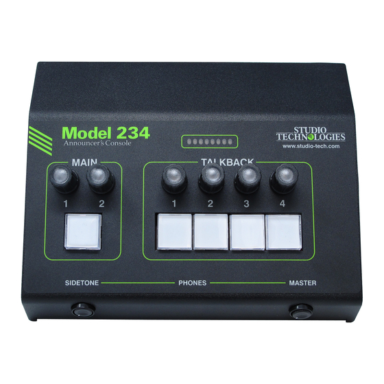
Model 234 Announcer's Console
User Guide
Issue Preliminary 2, July 2020
This User Guide is applicable for serial numbers
M234-00151 and later with main firmware version 1.02 and later
and STcontroller application version 2.10.00 and later.
Copyright © 2020 by Studio Technologies, Inc., all rights reserved
www.studio-tech.com
50686-0720 Issue Preliminary 2
Advertisement
Table of Contents

Related Manuals for Studio Technologies 234


Summary of Contents for Studio Technologies 234
- Page 1 This User Guide is applicable for serial numbers M234-00151 and later with main firmware version 1.02 and later and STcontroller application version 2.10.00 and later. Copyright © 2020 by Studio Technologies, Inc., all rights reserved www.studio-tech.com 50686-0720 Issue Preliminary 2...
- Page 2 This page intentionally left blank.
-
Page 3: Table Of Contents
Technical Notes ................20 Specifications ................. 25 Appendix A: STcontroller default configuration values ....27 Appendix B: 3-Pin Header Connector Details ........ 28 Appendix C: Model 234 Block Diagram .......... 29 Model 234 User Guide Issue Preliminary 2, July 2020 Studio Technologies, Inc. -
Page 4: Revision History
MODEL 234 ANNOUNCER’S CONSOLE Revision History Issue Preliminary 2, July 2020: • Second preliminary release. Issue Preliminary 1, June 2020: • Initial preliminary release. Issue Preliminary 2, July 2020 Model 234 User Guide Page 4 Studio Technologies, Inc. -
Page 5: Introduction
Ethernet switch with PoE capability will be utilized. It’s also possible to connect an external source of 12 volts DC to power the Model 234. If this is the case then a power supply would need to be provided separately. - Page 6 Refer to the Technical Notes section of this guide for details. An external source of 12 volts DC can be connected to the Model 234 by way of the One or Two Ethernet Connections 4-pin male XLR connector which is located One 1000BASE-T (“GigE”) Ethernet connection...
- Page 7 Another to the analog microphone output. No Model setting allows the gain of the preamplifier cir- 234 action will impact that signal. If the analog cuitry associated with the analog microphone microphone output is configured to follow the input to be selected.
-
Page 8: Dante Configuration
(a group of output channels) to a receiver on a 2-conductor (“tip and sleeve”) plug. When flow (a group of input channels). the plug is inserted into the Model 234’s head- Issue Preliminary 2, July 2020 Model 234 User Guide Page 8 Studio Technologies, Inc. - Page 9 (output) channels will function in multi- Redundancy cast; unicast is not supported.) The Model 234 allows connection of two Eth- Using Dante Controller, the desired Dante ernet signals. Two RJ45 jacks are located on transmitter (output) sources can be routed to the unit’s back panel and are labeled Primary-...
-
Page 10: Model 234 Configuration
The one or more Model operation. This requires the AES67 Mode to be 234 units to be configured will appear in the set for Enabled. By default, AES67 mode is set device list. Use the Identify command to allow for Disabled. - Page 11 P48 source is displayed both in STcontroller and by way of an orange LED that is located • System – Analog Mic Output on the Model 234’s back panel adjacent to the • System – Sidetone Mode analog microphone input connector. Select On or Off to meet the needs of the connected •...
- Page 12 The 8-segment LED audio level meter, located microphone input channel is utilized as the on the top of the front panel of the Model 234, Model 234’s microphone source. can also be used when setting the microphone preamplifier gain.
- Page 13 (output) level of –20 dBFS when is desired will depend on the amount of am- a typical audio signal is being provided on the bient light present where the Model 234 is Dante Mic In receiver (input) channel. located.
- Page 14 Model 234 then locally provided sidetone won’t be needed and the Off configuration On the Model 234’s back panel is a 3-pin male choice should be selected. The user will hear XLR connector that is labeled Mic Out. The...
- Page 15 An eight-LED bar-graph level display is pro- Remote Control In 1. When Main Button is vided on the front panel of the Model 234. selected activating Remote Control In 1 will It can display the level of the selected mi- provide the same function as pressing the crophone audio source.
- Page 16 It’s also possible in a LED will be lit. Whenever the main button is Issue Preliminary 2, July 2020 Model 234 User Guide Page 16 Studio Technologies, Inc.
- Page 17 Dante Talkback lit whenever the associated function is active, receiver (input) channel can be routed to red when it’s inactive. Upon Model 234 power the headphone outputs. This is a somewhat up the main button will be in its inactive state esoteric configuration but can prove useful in and its red LED will be lit.
- Page 18 Upon Model The 20 kHz sine wave will be combined with 234 power up the talkback button will be in its microphone audio and, if configured, the 18 inactive states and its LED will not be lit.
- Page 19 This might be ap- Selecting IFB (Dims Main Audio) allows a propriate if a Model 234 is being used as an broadcast type talent cue (IFB) function to be intercom station or stage manager console.
-
Page 20: Operation
If a DHCP server is not detected an IP sible to make a direct connection between address will automatically be assigned us- a personal computer and a Model 234. The ing the link-local protocol. This protocol is only additional piece of equipment necessary known in the Microsoft®... - Page 21 Two spare connector locations, labeled A phone input and microphone output connec- and B, are provided on the Model 234’s back tors should not be removed.) These 4-40 panel. From the factory each contains a blank...
- Page 22 To observe the firmware version numbers, To make the process of connecting to the begin by connecting the Model 234 unit to local Model 234’s headers an easy task an inter- area network (LAN). A source of 12 volts DC face cable kit, Studio Technologies’...
- Page 23 For the main firmware the file name must be M234.bin. For the secondary firmware the 5. After a few seconds the Model 234 will run file name must be M23Xsec.bin. And for the a “boot loader” program that will automati- FPGA firmware the file name must be BWY.bit.
- Page 24 Information selection under the Device tab.) Note that upon power being applied to the Model 234 if the USB flash drive doesn’t have the correct file(s) in its root folder no harm will occur. Upon power up the green LED, located...
-
Page 25: Specifications
USB: type A receptacle (used only for updating firmware) Maximum Output Voltage: 3.0 Vrms, 1 kHz, 150 ohm Remote Control Inputs / Tally Output: 2, 3-pin headers load located on the main circuit board Model 234 User Guide Issue Preliminary 2, July 2020 Studio Technologies, Inc. Page 25... - Page 26 Analog Microphone Input: 3-pin header located on the analog circuit board Spare Connector Locations: 2 Allows a Studio Technologies’ cable assembly or option module to be installed. Also compatible with Neutrik NC*D-L-1 connectors (*=3F, 3M, 5M, 6F, 6FS, etc.). Configuration: requires Studio Technologies’...
-
Page 27: Appendix A: Stcontroller Default Configuration Values
MODEL 234 ANNOUNCER’S CONSOLE Appendix A: STcontroller Default Model 234 Configuration Values General Menu Page: Microphone Input – Analog Mic In P48: Off Microphone Input – Source: Analog Mic In Microphone Input – Analog Gain: 50 dB System – Signal Present Display: All Inputs System –... -
Page 28: Appendix B: 3-Pin Header Connector Details
ANNOUNCER’S CONSOLE Appendix B: 3-Pin Header Connector Details The following list provides details on the 3-pin header connectors located on the Model 234’s printed circuit boards. Shown are both reference numbers and associated functions. I. Header on the Model 234’s Analog Board:... -
Page 29: Appendix C: Model 234 Block Diagram
MODEL 234 ANNOUNCER’S CONSOLE Appendix C: Model 234 Block Diagram The following block diagram shows a simplified version of the Model 234’s microphone input and microphone output circuitry. Model 234 User Guide Issue Preliminary 2, July 2020 Studio Technologies, Inc.
Need help?
Do you have a question about the 234 and is the answer not in the manual?
Questions and answers