Table of Contents
Advertisement
Quick Links
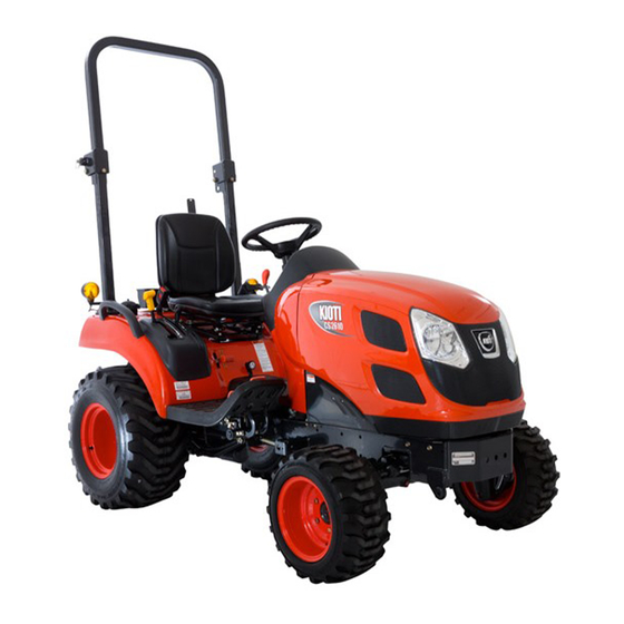
Congratulations, and welcome to the fabulous world of CS2610 ownership, where serious work is made fun
again!
This versatile tractor is a culmination of the entire tractor and diesel knowledge gained by the Daedong In-
dustrial Co.,LTD, since 1947 and has been designed with the finest materials, and quality control standard.
Knowledge of tractor operation is essential for many years of dependable service and reliability. To help new
owners familiarize themselves with the CS2610, it is the policy of KIOTI tractor to provide an owner's manual
which includes helpful information about tractor safety, operation and maintenance. If the information you seek
is not found in this manual, your KIOTI tractor dealer will be happy to help you.
Please feel free to contact DAEDONG-IND.CO.,LTD. with your questions/concerns.
< NOTe >
• Make sure to read this manual carefully and keep it reading accessible future reference.
• When leasing or transferring this tractor, deliver this manual together with the tractor.
• The specifications in this manual are subject to change without notice.
M46-EU,AU-EEC인증용-00.indd 1
FOReWORD
2017-03-10 오전 8:48:17
Advertisement
Table of Contents
Troubleshooting

Related Manuals for Daedong KIOTI CS2610


Summary of Contents for Daedong KIOTI CS2610
- Page 1 Congratulations, and welcome to the fabulous world of CS2610 ownership, where serious work is made fun again! This versatile tractor is a culmination of the entire tractor and diesel knowledge gained by the Daedong In- dustrial Co.,LTD, since 1947 and has been designed with the finest materials, and quality control standard.
- Page 2 TABLe OF CONTeNTS ISO 3600 eU STANDARDS This manual was compiled in compliance with the ISO 3600 standards and the instructions contained here comply with the requirements of the Machinery Directive 2010/52/EU in force in the European Community. For tractors sold or used outside the European Community, local laws will prevail.
- Page 3 SAFETY PRECAUTIONS ........ PRECAUTIONS BEFORE OPERATION ..SPECIFICATIONS ..........DESCRIPTION OF OPERATING SYSTEM ..SeCTION OPERATION ............ 3- POINT HITCH IMPLEMENT OPERATION .. MAINTENANCE ..........STORAGE AND DISPOSAL ......TROUBLESHOOTING ........INDEX ............... M46-EU,AU-EEC인증용-00.indd 3 2017-03-10 오전 8:48:17...
-
Page 4: Table Of Contents
TABLe OF CONTeNTS SAFeTY PReCAUTIONS ........1-1 DECalS ..............1-28 CaUTIONS FOR DECal MaINTENaNCE ....1-31 PReCAUTIONS BeFORe OPeRATION ....1-2 PReCAUTIONS BeFORe OPeRATION .....2-1 GENERal PRECaUTIONS ......... 1-2 vehICLe IDeNTIFICATION NUMBeR ....2-2 RISk OF OvERTURNING ........... 1-6 PReCAUTIONS DURINg OPeRATION ....1-9 PRODUCTION NUMbER .......... - Page 5 TABLe OF CONTeNTS IMPLeMeNT LIMITATIONS ........3-8 PaRkING bRakE WaRNING laMP ......4-13 PTO INDICaTOR (IF EQUIPPED) ......4-14 STaNDaRD IMPlEMENT DIMENSIONS ....3-8 4WD ENGaGED INDICaTOR (IF EQUIPPED) ..4-14 DeSCRIPTION OF OPeRATINg SYSTeM ..4-1 CRUISE laMP (OPTIONal) ........4-14 lOW RaNGE INDICaTOR (IF EQUIPPED) ....
- Page 6 TABLe OF CONTeNTS lIFTING aRM (lOWER lINk) SPEED CONTROl STOPPING ThE ENGINE ..........5-8 lEvER ..............4-25 WaRMING UP .............. 5-8 DOUblE aCTING lEvER (OPTIONal) ....4-25 JUMP STaRTING ThE ENGINE ........5-9 aUxIlIaRY PORT (OPTIONal) ........ 4-26 OPeRATINg The TRACTOR ......5-10 PTO ShaFT COvER &...
- Page 7 TABLe OF CONTeNTS ReMOvAL AND INSTALLATION OF 3-POINT LUBRICANTS ............7-7 hITCh IMPLeMeNT (WITh PTO ShAFT) ..6-2 MAINTeNANCe CODe ......... 7-8 MOWER IMPlEMENT ..........6-2 hOW TO DISCONNECT ThE hOOD (a) ....7-8 OPeRATION TIP FOR 3-POINT hITCh eLeMeNTS ..6-5 OPENING SIDE COvER (b) ........
- Page 8 TABLe OF CONTeNTS ChECkING WhEEl bOlT / NUT TORQUE (Q) ..7-21 DaIlY STORaGE ............8-2 REPlaCING aIR ClEaNER PRIMaRY ElEMENT (T) ..7-21 lONG-TERM STORaGE ..........8-2 ChECkING FUEl lINES (U) ........7-22 USINg TRACTOR AFTeR STORAge ....8-3 blEEDING FUEl SYSTEM (ak) ....... 7-23 USAge AND DISPOSAL ........
- Page 9 SAFeTY AND vehICLe DAMAge WARNINg This manual includes information titled as WARNING, CAUTION, IMPORTANT and NOTE. These titles indicate the following: This indicates that a condition may result in harm, serious injury or death to you or other persons if the warning is not heeded.
- Page 10 UNIveRSAL SYMBOLS Various universal symbols have been used on the instruments and controls of your KIOTI tractor. Below is a list of the universal symbols and their meanings. Power Take-off Clutch Con- Fuel-level Preheat trol-on Position Parking brake Differential lock h: high Speed Travel light battery Charging Condition hazard Warning lights...
-
Page 11: Safety Precautions
SAFETY PRECAUTIONS PRECAUTIONS bEFORE OPERATION ...... 1-2 General precautions ............1-2 risk of overturninG ............1-6 PRECAUTIONS dURINg OPERATION ....... 1-9 When startinG the enGine ..........1-9 When drivinG the tractor ..........1-13 When parkinG the tractor ..........1-15 When operatinG the pto ..........1-15 When usinG the 3-point hitch ........1-16 SAFETY PRECAUTIONS dURINg SERvICINg .. -
Page 12: Precautions Before Operation
cs2610 PRECAUTIONS bEFORE OPERATION gENERAl PRECAUTIONS a careful operator is the best opera- tor. most accidents can be avoided safety helmet by observing certain precautions. to help prevent accidents, use these fit clothes safety precautions, and pay attention to the job at hand. if you can prevent tight sleeves an accident, your time will have been well spent. - Page 13 safetY precautions a careful operator is the best opera- tor. most accidents can be avoided by observing certain precautions. to help prevent accidents, use these safety precautions, and pay attention to the job at hand. if you can prevent an accident, your time will have been well spent.
- Page 14 cs2610 T66O103a T66O104a T66O105a 9. never operate this tractor or 12. never start the engine while 16. all persons using the tractor any other agricultural equipment standing on the ground. should have knowledge of its while under the influence of alco- proper operation and should read 13.
- Page 15 safetY precautions NOTE • always use seat belt when the tractor is equipped with a ROPS and CAb. NEvER USE ThE SEAT bElT whEN TRACTOR IS NOT EQUIPPEd wITh A ROPS. (ROPS: roll-over pro- tective structures) a ROPS and CAb should never be T66O106a T66O107a modified by welding, grinding or cut-...
-
Page 16: Risk Of Overturning
cs2610 RISK OF OvERTURNINg ImPORTANT • The safe working practices listed hereunder concerns only a few cases of overturn- ing risk. • The list is therefore NOT com- prehensive of all possible cases. T55O116a Tg2O103a 22. this cabin is not certified for for your safety, tractors must be chemical proof, never operate equipped with original safety belts. - Page 17 safetY precautions • reduce your speed before making wide turns. do not let the tractor jump or bounce on rough terrains. You could lose control. • don't pull a load too heavy for your tractor. it could run away on the down slope or the tractor could jack-knife around a towed load.
- Page 18 cs2610 Tg2O107a Tg2O108a • if you need cross a steep slope, • When driving across a slope with do not steer uphill, but slow down mounted implements, keep such and take a wide turn. always drive implements on the uphill side. do straight up or down a slope, never not raise implements.
-
Page 19: Precautions During Operation
safetY precautions PRECAUTIONS dURINg OPERATION whEN STARTINg ThE ENgINE Tg2O109a M46O108a T66O108a 1. enter or leave the tractor leftward 2. avoid accidental contact with gear • avoid crossing steep slopes if pos- griping hand rail on a fender. shift levers while the engine is run- sible. - Page 20 cs2610 T66O109a T66O110a M46O107a (1) draw-bar (2) towing hook 3. do not park your tractor on a steep 4. do not operate your tractor in an 5. make sure that all pressure lines incline, and remember to shut enclosed building without the prop- are tight before starting the tractor.
- Page 21 safetY precautions using the proper adaptor parts, attach the chain to the tractor draw-bar support or other speci- fied anchor location. Provide only enough slack in the chain to per- mit turning. see your dealer for a chain with a strength rating equal to, or greater than the gross weight of the towed machine.
- Page 22 cs2610 16. When using implements or at- tachments with your tractor you should first read their respective owner's manual. You should al- ways keep their safe operation procedures in mind. 17. YOU ShOUld bE FAmIlIAR wITh YOUR EQUIPmENT ANd ITS lImITATIONS. 18.
-
Page 23: When Driving The Tractor
safetY precautions whEN dRIvINg ThE TRACTOR T66O114a T66O115a M46O102a (1) Brake pedal (2) parking Brake 19. driving forward out of a ditch 21. When working in groups, always 1. depress the brake pedal firmly or steep inclines can cause the let the others know what you are when making an emergency stop. - Page 24 cs2610 7. do not apply the differential lock while traveling at road speeds the tractor may run out of control. 8. avoid sudden movements of the steering wheel as this can cause a loss of control of the tractor. this risk is especially great when traveling at road speeds.
-
Page 25: When Parking The Tractor
safetY precautions whEN PARKINg ThE TRACTOR whEN OPERATINg ThE PTO shop manual and review the safety labels attached to the equipment. wARNINg • before driving an implement through the PTO, always make sure that all bystanders are well away from the tractor. •... -
Page 26: When Using The 3-Point Hitch
cs2610 SAFETY PRECAUTIONS dURINg SERvICINg whEN USINg ThE 3-POINT hITCh T66O122a T66O124a M46O105a (1) 3-point hitch lowering speed knob (a) fast (B) sloW 4. When operating stationary pto 1. use the 3-point hitch only with in order to service your tractor you driven equipment, always apply equipment designed for 3-point must park it on a flat level surface, set... - Page 27 safetY precautions T66O125a T66O126a M55O114a 2. allow the tractor time to cool "off" be- 6. do not remove the radiator cap 7. if the tractor must be lifted for fore servicing any part that may have while the coolant is hot. When servicing, take it to a suitably become hot while the tractor is running.
- Page 28 cs2610 NOTE • apply the jack lift to the lifting points according to the type of operation and follow the safety procedures given before. M55O115a T66O127a 10. use jack lifts of suitable capac- 15. When working with your trac- ity and apply them at the center tors electrical components you of the front and rear axles while must first disconnect the battery...
- Page 29 safetY precautions all connections are tight and that all lines, pipes and hoses are free of damage. T66O128a T66O129a (1) card Board (2) hydraulic line (3) magnifying Glass 17. tire mounting should be done by 20. make sure that wheel bolts have qualified professionals, with the been tightened to the specified proper equipment.
-
Page 30: Safety Precautions When Using The Loader
cs2610 SAFETY PRECAUTIONS whEN USINg ThE lOAdER T66O130a T66O131a H11O102a 22. FlUId ESCAPINg FROm PIN- 23. keep environmental pollution in 1. never let anyone get in the loader hOlES mAY bE INvISIblE. dO mind. When replacing coolant or and use the loader as a worksta- NOT USE hANdS TO SEARCh oil, dispose of it the right way. - Page 31 safetY precautions H11O103a H11O104a H11O105a 2. do not stand under the lifted load- 3. the loader can be turned over if a 4. never carry a big object with the er or get close to it. also, lower the drawbar is improperly loaded. loader unless a proper implement loader arm onto the ground before is attached.
- Page 32 cs2610 H11O106a H11O107a H11O108a 5. When attaching or detaching the 6. do not allow loader arms or attach- 7. keep bystanders away. no riders. loader, fix all parts which are con- ment to contact electrical power nected to the bucket and boom. lines.
-
Page 33: Implements And Attachments
safetY precautions ImPlEmENTS ANd ATTAChmENTS ImPORTANT WARNING • • Use exclusively front loader Keep the loader's operation approved by the tractor's man- manual together with the trac- ufacturer, with CE mark and tor's manual, always at hand parallelogram type. in the storage compartment of •... - Page 34 cs2610 • three-point hitch and side mounted swinging and shaking during trans- implements make a much larger port and work that could jeopardize arc when turning than towed equip- the stability of the tractorimplement ment. make certain to maintain assembly. enough clearance for safe turning.
- Page 35 safetY precautions to reduce risks, the following precau- • check for correct coupling between tions should be used. tow hook and trailer. see the tow- ing attachments section. - only use loader equipped with a load self-levelling system, i.e. of the •...
-
Page 36: Cleaning The Tractor
cs2610 ClEANINg ThE TRACTOR • keep work surfaces and engine compartments clean. • Before cleaning the machine, always lower implements to the ground, engage the first gear, engage the parking brake, turn the engine off and re- move the key. •... -
Page 37: Safety Decal Maintenance
safetY precautions SAFETY dECAl mAINTENANCE dECAl mOUNTINg lOCATION M46O106a M46-EU,AU-EEC인증용-01.indd 27 2017-03-10 오전 8:14:43... -
Page 38: Decals
cs2610 dECAlS (1) part no.: t2555-52281 (2) part no.: t4625-52351 (4) part no.: t2555-52331 DANGER Start engine only from operators seat, If safety start switch is bypassed engine can start with transmission in gear. Do not connect or short across terminals on starter solenoid. - Page 39 safetY precautions (6) part no.: t2555-52141 (7) part no.: t4182-53191 (9) part no.: t2555-52471 WARNING WARNING TO AVOID POSSIBLE INJURY, DEATH OR LOSS OF PROPERTY FROM A MACHINE RUNAWAY Before starting and operating With the engine off, unepected machine movement could - Know the operating and safety instructions result regardess of the gear shift position.
- Page 40 cs2610 (11) part no.: t2555-52351 D A N G E R Improper operating of tractor can rollover Lower the ROPS for low clearance ONLY. RAISE ROPS and insert locking pin immediately or upset after low clearance use, or for transport - DO NOT fold ROPS with a conopy attached.
-
Page 41: Cautions For Decal Maintenance
safetY precautions CAUTIONS FOR dECAl mAINTENANCE safety decals are attached to the ImPORTANT tractor for safe operation. make sure • If a decal is damaged or lost, to follow the instruction on the decals contact your local KIOTI deal- as well as the following instruction: er immediately to install a new CAUTION decal. - Page 42 memo mEmO M46-EU,AU-EEC인증용-01.indd 32 2017-03-10 오전 8:14:46...
-
Page 43: Precautions Before Operation
Precautions before oPeration Vehicle identification number ......2-2 Production number ............2-2 engine number ..............2-2 transmission number ............2-2 essential rePlacement Parts ......2-4 oils and fluids ..............2-4 filters ..................2-4 belts and rubber Parts.............2-5 other comPonents .............2-5 M46-EU,AU-EEC인증용-02.indd 1 2017-03-10 오전 8:17:17... -
Page 44: Vehicle Identification Number
cs2610 Vehicle identification number transmission number Production number engine number M46O201c M46O202A M46O203A (1) S/N Identification Plate (1) Engine Serial Number (1) Transmission Serial Number This number is to identify the vehicle, It is also stamped on the mounting The transmission number is stamped and its plate is attached on the front surface of the injection pump as a on the transmission case on the PTO... - Page 45 Precautions before oPeration Your dealer is interested in your new • tractor model name: tractor and has the desire to help you get the most value from it. After reading this manual thoroughly, you • tractor serial no: will find that you can do some of the regular maintenance yourself.
-
Page 46: Essential Replacement Parts
Make sure to replace the these items °c Engine Oil SAE 15W40(above -10 3.0 (0.8) when changing oil. daedong utf55 Transmission Exxonmobil Mobilfluid 424 Part no descriPtion 13 (3.4) fluid BP: Tractran UTH Exxonmobil Hydraulic 560... -
Page 47: Belts And Rubber Parts
Precautions before oPeration belts and rubber Parts other comPonents H11O206A H11O207A Belts, hoses and boots, which are The battery is a very important con- made of rubber, get weakened and sumable component that supplies cracked as they age. If these parts power to the alternator when the en- remain in this state, they can be gine is started. - Page 48 memo memo M46-EU,AU-EEC인증용-02.indd 6 2017-03-10 오전 8:17:19...
-
Page 49: Specifications
specifications General specifications ........3-2 ExtErnal dimEnsions ............3-2 maJor sPECiFiCations ............3-3 noisE lEvEls as PErCEivEd by thE oPErator .....3-6 vibration lEvEls oF thE traCtor ExPosition to vibrations ................3-7 iMpleMent liMitations .......... 3-8 standard imPlEmEnt dimEnsions ........3-8 M46-EU,AU-EEC인증용-03.indd 1 2017-04-27 오전 9:07:50... -
Page 50: General Specifications
Cs2610 General specifications external diMensions mm (in.) iteM cs2610 1. overall length (a1) 2,800 (110.23) 2. overall length (a2) 2,523 (99.33) 3. overall width (b) 1,270 (50.00) 4. overall height (C1) 1,899 (74.76) 5. overall height (C2) 2,280 (89.76) 6. Wheel base (d) 1,400 (55.12) 7. -
Page 51: Major Specifications
sPECiFiCations MaJor specifications iteM cs2610 reMarKs model s773l-EU number of cylinders total displacement 1,131 bore and stroke mm (in.) 77 x 81 (3.0 x 3.2) Engine gross power hP (kW) 26.0 (19.4) Pto Power hP (kW) 20.5 (15.3) rated revolution 3,000 Fuel tank l (U.s.gal.) - Page 52 Cs2610 iteM cs2610 reMarKs Forward 3,000 rpm 0~16.6 (0~10.3) Ground speed km/h (mph) (tire for industrial) reverse 3,000 rpm 0~11.2 (0~7.0) 4-wheel drive mechnical Quick turn (Qt) none brake Wet disk type differential lock standard for rear axle Front agricultural rear Front 18 x 8.5 - 8 r4...
- Page 53 sPECiFiCations Model cs2610 reMarKs 61cm (24in.) behind kg (lbs.) 318 (700) max. lifting capacity lower link end kg (lbs.) 715 (1,580) type independent rear Pto shaft 1- 3/8" 6 splines speed (Ptorpm / engine rpm) 540/3,000 Pto shaft (*) 16/32" 15 splines mid (optional) speed (Pto rpm@engine rpm) 2,200@3,020...
-
Page 54: Noise Levels As Perceived By The Operator
Cs2610 noise levels as perceived by the operator the following tables give the noise level values, measured from the driver’s seat in instantaneous conditions in com- pliance with standards 2009/76/EC (dba) - annex ii (without load) - and when driving by in compliance with standard 2009/63/EC (dba) tractors without cabin directive of the european... -
Page 55: Vibration Levels Of The Tractor Exposition To Vibrations
sPECiFiCations vibration levels of the tractor exposition to vibrations WarninG • the vibration level transmitted to the body as a whole depend on different parameters, some of them relat- ing to the machine, others to the terrain and many specific for the operator. The prevailing parameters are the type of terrain or work surface and the ground speed. -
Page 56: Implement Limitations
Cs2610 iMpleMent liMitations standard iMpleMent diMensions this Kioti tractor has been thoroughly tested for proper performance with implements sold or approved by Kioti. Use with implements which are not sold or approved by Kioti and which exceed the maximum specifications listed below, or which are otherwise unfit for use with this Kioti tractor may result in malfunctions or failures to the tractor, damage to other property and injury to the operator or others. - Page 57 Cutting width 2,133 (84) note : this is a sample of attachments commonly used. before purchasing or using any attachment on a daedonG product, please review the specifications to determine if it is a compatible product. Damages or failures due to improper use of compatibility issue will not be covered by warranty.
- Page 58 mEmo MeMo M46-EU,AU-EEC인증용-03.indd 10 2017-04-27 오전 9:07:54...
- Page 59 DESCRIPTION OF OPERATING SYSTEM ExTERIOR vIEw ......... 4-3 CrUIse LAMp (OpTIONAL) ...... 4-14 LOw rANGe INdICATOr (IF eQUIpped) ..4-15 MOUNTING LOCATION ....... 4-4 NeUTrAL INdICATOr (IF eQUIpped) ..4-15 Key swITCh ..........4-4 hIGh rANGe INdICATOr (IF eQUIpped) ..4-15 COMbINATION swITCh ......4-6 hAzArd LAMp swITCh ......
- Page 60 DESCRIPTION OF OPERATING SYSTEM AUxILIAry pOrT (OpTIONAL) ....4-26 pTO shAFT COVer & CAp ...... 4-26 ACCESSORY SYSTEM ..... 4-26 CUp hOLder ..........4-26 TOOL bOx..........4-27 TIRES, wHEElS AND bAllAST ..4-27 INFLATION pressUre ......4-28 TreAd............4-29 wheeL TOrQUe ANd dIreCTION ..4-29 AddITIONAL weIGhT (OpTIONAL) ....4-29 M46-EU,AU-EEC인증용-04.indd 2 2017-06-16 오후...
-
Page 61: Description Of Operating System
desCrIpTION OF OperATING sysTeM ExTERIOR vIEw M46O401A (1) seat (5) head Lamp (9) Top Link (13) draw bar (2) steering wheel (6) rOps (10) pTO shaft Cover (14) Lower Link (3) Fuel Tank Cap (7) Turn signal Lamp (11) Crank Lifting rod (4) bonnet (8) Fender (12) Check Link... -
Page 62: Mounting Location
Cs2610 MOuNTING lOCATION KEY SwITCH M46O403A (1) Key switch (A) pre-heat (b) stop (C) ACC (d) ON (e) start • The position "A" indicates the "manual preheat". This position is a self-return type, so the key should be held there while pre- heating. - Page 63 desCrIpTION OF OperATING sysTeM • NOTE IMPORTANT when the key switch is in position • • The pre-heating operation will To start the engine, place the "b", the engine and all electrical automatically be activated in this range shift lever in the neutral devices in the vehicle are turned position "d"...
-
Page 64: Combination Switch
Cs2610 COMbINATION SwITCH HEAD lIGHT SwITCH CAuTION • Stop the engine immediately if the oil pressure warning lamp does not go off after the engine is started. The engine may be severely damaged. • If the battery charge warning lamp does not go off after the engine is started, check the elec- trical systems, such as the alter- M46O404A... -
Page 65: Hazard Lamp Switch
desCrIpTION OF OperATING sysTeM HAzARD lAMP SwITCH TuRN SIGNAl lIGHT SwITCH HORN SwITCH M46O406A M46O407A M46O408A (1) Turn signal Light switch (1) horn switch (1) hazard Lamp switch (A) right Turn (b) Left Turn (A) ON (b) OFF The turn signal lights are used when The horn switch can be operated This switch can be used to warn turning the vehicle left or right. -
Page 66: Cruise Operation Switch (Optional)
Cs2610 CRuISE OPERATION SwITCH (OPTIONAl) CAuTION wARNING • • Never use the cruise control If the hazard lamps are turned on for an extended period function on a public or bumpy of time while the engine is road or during turning. stopped, the battery can be discharged. -
Page 67: Instrument Panel
desCrIpTION OF OperATING sysTeM INSTRuMENT PANEl vIEw symbols on the instrument panel come on when the key switch is turned to the "ON" position. M46O410A (1) Low speed Indicator (7) high speed Indicator (13) battery Charge warning Lamp (19) Quick Turn Lamp (2) Neutral Indicator (8) Coolant Temperature Gauge (14) engine Oil pressure warning Lamp... -
Page 68: Tachometer / Hour Meter Indicator
Cs2610 TACHOMETER / HOuR METER FuEl GAuGE INDICATOR NOTE • Make sure to use only correct fuel as the engine can be dam- aged if unqualified fuel is used. • Use fuel for winter season in cold weather to start the engine easier. -
Page 69: Engine Coolant Temperature Gauge
desCrIpTION OF OperATING sysTeM ENGINE COOlANT TEMPERATuRE GAuGE ENGINE OIl PRESSuRE wARN- ING lAMP CAuTION • Make sure to control the work load so that the needle is not in the red zone. • If the needle stays in the red zone with buzzer, do not stop the engine immediately. -
Page 70: Battery Charging Lamp
Cs2610 bATTERY CHARGING lAMP HEAD lIGHT HIGH bEAM INDI- CATOR CAuTION • If the oil level is below the specified range, the engine can seize. • The engine can be severely damaged if driving or operat- ing the tractor with the engine oil warning lamp "ON". -
Page 71: Turn Signal Lamp
desCrIpTION OF OperATING sysTeM TuRN SIGNAl lAMP GlOw PluG INDICATOR PARKING bRAKE wARNING lAMP M46O414A M46O420A M46O419A Operating the turn signal lamp switch This indicates the operating condition when the parking brake is actuated, turns on the corresponding lamp in of the preheat system. -
Page 72: Pto Indicator (If Equipped)
Cs2610 PTO INDICATOR (IF EQuIPPED) 4wD ENGAGED INDICATOR (IF CRuISE lAMP (OPTIONAl) EQuIPPED) M46O416A M46O415A M46O451A This indicator shows the pTO en- This comes on to indicate 4wd en- 1. Operating condition gagement condition. when the pTO gagement. Turn on the cruise switch during is engaged, this indicator comes on. -
Page 73: Low Range Indicator (If Equipped)
desCrIpTION OF OperATING sysTeM lOw RANGE INDICATOR (IF NEuTRAl INDICATOR (IF HIGH RANGE INDICATOR (IF EQuIPPED) EQuIPPED) EQuIPPED) M46O422A M46O423A M46O425A If the range shift is at low speed, this If the range shift is in neutral posi- If the range shift is at high speed, lamp illuminates in green. -
Page 74: Operating The Controls
Cs2610 OPERATING THE CONTROlS (1) hand Throttle Lever (2) brake pedal (3) parking brake Lock Lever (4) hsT Forward pedal (5) hsT reverse pedal (6) range Gear shift Lever (7) differential Lock pedal (8) 3-point hitch Lowering speed Knob (9) double Acting Lever (A, b) (10) Lift position Control Lever (11) pTO Clutch Lever (12) pTO select Lever... -
Page 75: Hst Range Gear Shift Lever
desCrIpTION OF OperATING sysTeM HST RANGE GEAR SHIFT lEvER bRAKE PEDAl 3. shift the range shift lever into the desired position with the brake pedal and front / rear driving ped- als depressed. CAuTION • Never put the range shift lever into the high speed position during driving backward as it is dangerous to drive at a high... -
Page 76: Parking Brake Lever
Cs2610 PARKING bRAKE lEvER FRONT wHEEl DRIvE lEvER 4. when the tractor is pushed out by reaction from the implement during cultivating on a hard surface. 5. When cultivating a field or driving over a bank. be sure to full stop the tractor before engaging or disengaging the 4wd. -
Page 77: Forward / Reverse Driving Pedals
desCrIpTION OF OperATING sysTeM FORwARD / REvERSE DRIvING PEDAlS HAND THROTTlE lEvER IMPORTANT • For heavy load job, such as front end loader operation, use low speed of the range shift lever. M46O432A M46O431A (1) hand Throttle Lever (1) Forward / reverse driving pedals : decrease : Increase (A) Forward... -
Page 78: Differential Lock Pedal
Cs2610 DIFFERENTIAl lOCK PEDAl Use this system under the following CAuTION conditions: • using the accelerator lever 1. when any wheel slips and the during driving can lead to an tractor does not move in the field. accident as it becomes hard to 2. -
Page 79: Pto Shift Lever
desCrIpTION OF OperATING sysTeM PTO SHIFT lEvER CuTTING HEIGHT ADJuSTMENT lEvER IMPORTANT • Deck must be in the "full up" position before cutting height can be changed. Do Not at- tempt to change cutting height with deck in any other position than "full up". -
Page 80: Pto Clutch Lever
Cs2610 PTO CluTCH lEvER Gauge wheels must be adjusted ac- NOTE cording to the cutting height setting. • To change pTO selection, the Use the following chart for gauge pTO clutch should be disen- wheel position. gaged. Also, it should be disen- FRONT and REAR gaged when trying to start the CuTTING HEIGHT... -
Page 81: Seat Adjustment
desCrIpTION OF OperATING sysTeM SEAT ADJuSTMENT SEAT SlIDING SEAT bElT IMPORTANT • The seat is equipped with a safety device that stops the engine when the driver's seat is not occupied. • If you leave the seat without applying of parking brake, warning buzzer will sound and parking lamp also will blink for 10 seconds. -
Page 82: Hydraulic System
Cs2610 HYDRAulIC SYSTEM POSITION CONTROl lEvER lower a 3-point hitch implement. wARNING To lower an implement, move the • Make sure that the seat belt lever forward. To raise an implement, is not twisted. It cannot work move the lever backward. properly, leading to a danger- The position control lever is automat- ous situation. -
Page 83: Lifting Arm (Lower Link) Speed Control Lever
desCrIpTION OF OperATING sysTeM lIFTING ARM (lOwER lINK) DOublE ACTING lEvER (OPTIONAl) SPEED CONTROl lEvER M46O439A M46O440A M46O448A (1) Lowering speed control lever (1) double Acting Lever (1) Quick Coupler (A) high speed (b) Low speed (A) port A (b) port b Turning the lever counterclockwise This lever is used to control a auxil- wARNING... -
Page 84: Auxiliary Port (Optional)
Cs2610 ACCESSORY SYSTEM AuxIlIARY PORT (OPTIONAl) PTO SHAFT COvER & CAP CuP HOlDER M46O449A M46O441A (1) pTO shaft Cover (2) pTO shaft Cap (1) Cup holder Use only the double mounting full The cup holder is installed to the left type pTO cover. -
Page 85: Tool Box
desCrIpTION OF OperATING sysTeM TIRES, wHEElS AND bAllAST TOOl bOx T85O530A T46w030A M46O442A (1) Tool box (A) Insufficient (B) Standard (C) excessive The toolbox with latch cover is lo- Though the tire pressure is factory-set wARNING cated in front of the vertical ROPS to the prescribed level, it naturally drops •... -
Page 86: Inflation Pressure
Cs2610 INFlATION PRESSuRE Always maintain the proper tire inflation pressure. Make sure the tire pressure does not exceed the pressure recommended in the manual. CS2610 ITEM Tire sizes Inflation pressure Farm Front Turf 18 x 8.5 - 8 r3 0.6~1.4 kg/cm², 60~140 Kpa, 8.7~20.3 psi 18 x 8.5 - 8 r4 0.6~1.4 kg/cm², 60~140 Kpa, 8.7~20.3 psi Farm... -
Page 87: Tread
desCrIpTION OF OperATING sysTeM TREAD wHEEl TORQuE AND DIRECTION ADDITIONAl wEIGHT (OPTIONAl) wHEEl bOlT AND NuT TORQuE ADDITIONAl FRONT wEIGHT Front 8.97 kgf·m (88 N·m) Rear 12.44 kgf·m (122 N·m) wARNING • use tires approved by KIOTI only. • Assemble the tire as shown in the figure. - Page 88 Cs2610 COMPONENTS FOR ADDITIONAl FRONT wEIGHT If the front tires are heavily loaded CAuTION and it becomes hard to steer the • Additional weight might be tractor, the tires can be worn faster needed for transporting heavy and the durability of the front axle implements.
- Page 89 desCrIpTION OF OperATING sysTeM ADDITIONAl lIQuID TYPE wEIGHT It is possible to inject water and cal- NOTE cium solution into the tire to use it as • If the liquid ballast is used, inflate a ballast. the tire 0.14 bar (2 psi) more NOTE than the specified pressure.
- Page 90 MeMO MEMO M46-EU,AU-EEC인증용-04.indd 32 2017-06-16 오후 1:07:10...
-
Page 91: Operation
OPERATION PRE-OPERATION......... 5-2 poWER STEERING pRECAuTIoNS ..5-19 3-poINT HITCH CoNTRol SySTEm ..5-21 INITIAl.OPERATION......5-3 ExTERIoR HyDRAulIC CoNTRol SyS- TEm (opTIoNAl) ........5-23 OPERATING.THE.ENGINE....5-3 STARTING THE ENGINE ......5-3 SToppING THE ENGINE ......5-8 WARmING up .......... -
Page 92: Pre-Operation
CS2610 PRE-OPERATION CHECk.ITEm It is a good practice to know the con- .•.Walk around inspection. For detailed information, refer to dition of your tractor before you start "maintenance interval" in chapter 7. .•.Check the engine oil level. it. you should do a routine check be- .•.Check the transmission oil level fore each use. -
Page 93: Initial Operation
opERATIoN INITIAl.OPERATION OPERATING.THE.ENGINE STARTING.THE.ENGINE TIPS.fOR.BREAkING-IN Driving a new tractor at a high speed 1. Break in the vehicle within initial 50 WARNING or load can damage its overall dura- hours of operation. To.avoid.accidents: bility. 2. Start the engine and idle the en- •... - Page 94 CS2610 ImPORTANT • make.sure.that.the.brake.pedals. are.fully.depressed.before.pull- ing.the.parking.brake.lever.up. M46O447A (1) parking Brake lever (2) Brake pedal (A) Depressing (B) pressing up 1. make sure there is no hazardous obstacle around the tractor. 2. make sure the parking brake is set (1) Depress the parking brake ped- al and pull the lever up.
- Page 95 opERATIoN 5. Set range shift lever in the neutral position. (It cannot be started while the range gear or pTo is engaged) M46O501A M46O431A (1) position Control lever (1) Hand Throttle lever (A) Down : Decrease : Increase 6. lower the attachment by pushing 7.
- Page 96 CS2610 warning lamps come on when the WARNING key is in "oN" position before the • Never. operate. the. start. motor. engine start. for. more. than. 10. consecu- NOTE tive. seconds. as. it. consumes. an. excess. of. battery. power.. If. operating principle of auto pre- the.
- Page 97 opERATIoN ENGINE.CHECk.lAmPS 1. If the oil pressure warning lamp (2) WARNING does not go "oFF" in 4 to 5 sec- • If.driving.the.tractor.for.an.ex- onds after the engine is properly tended.period.of.time.with.the. started, stop the engine immedi- charge. warning. lamp. "ON",. ately and check the engine oil lev- the.battery.can.be.discharged.
-
Page 98: Stopping The Engine
CS2610 STOPPING.THE.ENGINE WARmING.UP It is recommended always to warm WARNING up the engine before driving in or- • Never touch the muffler or hot der to maintain the durability of the covers. until. they. are. cooled. engine and prevent malfunction of down.after.running.the.engine. -
Page 99: Jump Starting The Engine
opERATIoN JUmP.STARTING.THE.ENGINE HOW.TO.WARm.UP.ENGINE 1. Start the engine and run it at a low WARNING speed and without load for approx. • Warming. up. the. engine. ex- 3 to 4 minutes. cessively. increases. fuel. con- 2. In cold weather, increase the sumption.and.affects.the.dura- warming up time to 10 minutes. -
Page 100: Operating The Tractor
CS2610 OPERATING.THE.TRACTOR DRIvING 1. Check that the voltage of the dis- nect the clip to a part of the frame charged battery is same as the without paint. voltage of the other tractor or ve- 6. Start the engine of the tractor hicle for jump start. - Page 101 opERATIoN H11O511A M46O505A M46O431A (1) Seat Belt (1) position Control lever (1) Hand Throttle lever (A) lifting : Decrease : Increase 2. Wear the seat belt. 3. pull the position control lever back- 4. Increase slowly the engine Rpm ward to raise the attachment. from idle speed to medium speed.
- Page 102 CS2610 CAUTION • D o. n ot. c h a ng e. th e. t racto r. speed. abruptly. for. safe. driv- ing. • When. driving. on. a. slope. or. loading. or. unloading. the. trac- tor. to. a. transporting. vehicle,. reduce.
-
Page 103: Folding The Rops
opERATIoN fOlDING.THE.ROPS CAUTION • It. is. very. dangerous. to. drive. with.the.ROPS.folded..fold.the. ROPS. only. when. there. is. ab- solutely. no. possibility. for. roll. over.. If. the. situation. changes,. unfold.the.ROPS.immediately. M46O507A M46O508A (1) Grip Bolt (2) Set pin (1) RopS 1. pull the set pin forward. 2. -
Page 104: Raising The Rops To Upright Position
CS2610 RAISING.THE.ROPS.TO.UPRIGHT.POSITION M46O509A M46O510A M46O507A (1) Grip Bolt (2) Set pin (1) Grip Bolt (2) Set pin 3. Align it to the groove and pull the 1. pull the set pin forward. 3. Align it to the groove and pull the set pin to release it. -
Page 105: Parking
opERATIoN PARkING 6. If it is necessary to park the tractor 2. pull the parking brake lever (2) up on a slope with the engine running, with the brake pedals depressed chock all four wheels (1) and per- fully to engage the pedals with the form Steps 3 and 4 above. -
Page 106: Turning
CS2610 TURNING DRIvING.ON.SlOPE you should turn slowly by lowering 1. please drive according to the con- ImPORTANT the engine rotation if possible. ditions of the slope at safe speed • The. tractor. may. move. slowly. so that the engine is not under WARNING with. -
Page 107: Cautions Concerning Paved Road
opERATIoN CAUTIONS.CONCERNING.PAvED.ROAD 5. It is recommended to use the 4WD WARNING and drive backward when moving • make. sure. that. the. coupling. onto a bank. device.of.brake.pedal.and.dif- ferential. lock. pedal. are. surely. released. • Before.entering.a.steep.slope,. move. the. shift. lever. down. to. a. -
Page 108: Precautions While Driving On The Road
CS2610 PRECAUTIONS.WHIlE.DRIvING.ON.THE.ROAD WARNING • If. the. tractor. breaks. down. while. driving. on. the. road,. move.it.to.a.safe.place.to.ser- vice.. If. not,. it. can. cause. per- sonal.injury. M46O512A M46O512A (1) Direction Indicator (Rear) (1) Brake pedal 1. When you change the driving di- WARNING rection on the road, let other car •... -
Page 109: Loading Into And Unloading Out Of The Truck
opERATIoN lOADING.INTO.AND.UNlOADING.OUT.Of.THE.TRUCk POWER.STEERING.PRECAU- TIONS WARNING • When. transporting. the. trac- tor with a truck, fix the tractor firmly onto the truck and and be.sure.to.aware.the.height.of. loaded. tractor. to. avoid. to. hit. the.ceiling.of.the.tunnel.or.the. bottom.of.the.bridge.. • make. sure. to. follow. this. in- struction. as. such. accidents. yyyO186A M46O514A really.happen. - Page 110 CS2610 wheel operation can be somewhat NOTE NOTE difficult. Operate the steering while • The power steering system in this T h e n o n - l o a d r e a c t i o n t y p e tractor is in motion.
-
Page 111: 3-Point Hitch Control System
opERATIoN 3-POINT.HITCH.CONTROl.SySTEm WARNING WARNING • • When.driving.on.a.road.with.an. If. stopping. the. engine. while. implement. attached. to. the. rear. driving,. the. steering. perfor- of. the. tractor,. the. traction. of. mance. can. become. deterio- the.front.wheels.becomes.poor,. rated. due. to. loss. of. hydraulic. resulting.in.poor.steer.ability..In. power,. resulting. in. a. severe. this.case,.attach.a.proper.front. - Page 112 CS2610 POSITION.CONTROl 4. The lower link is lifted by the hy- draulic energy of the tractor while it is lowered by potential energy of its own weight. Therefore, the implement cannot be lowered by the hydraulic pressure. 5. Therefore, the implement attached to the lower link may be lifted by protrusion on the ground when it is lowered to the ground.
-
Page 113: Exterior.hydraulic.control.system.(Optional)
opERATIoN ExTERIOR.HyDRAUlIC.CONTROl.SySTEm.(OPTIONAl) DOUBlE.ACTING.vAlvE.lEvER kIOTI supplies two types of the ImPORTANT double acting valves by region: self- • Put. the. detent. valve. operating. return type and detent type. lever. into. the. neutral. position. • For the self-return type double act- when. the. hydraulic. implement. ing lever, it returns to its original is.not.in.use..If.the.detent.valve. - Page 114 CS2610 SINGlE.ACTING.AND.DOUBlE.ACTING.CylINDER 3. When the cylinder is contracted, the hydraulic fluid returned from the cylinder is drained to the trans- mission through the draining circuit as the operating lever is operated to the opposite direction from the expansion position. ImPORTANT •...
- Page 115 opERATIoN CONNECTING.AND.DISCONNECTING.ImPlEmENT.HyDRAUlIC.HOSE CONNECTION DISCONNECTION WARNING 1. make sure to stop the engine be- 1. make sure to stop the engine be- • Never. connect. or. disconnect. fore connecting hydraulic hoses. fore disconnecting implements. the. implement. hydraulic. hose. 2. move the double acting valve le- 2.
- Page 116 mEmo mEmO M46-EU,AU-EEC인증용-05.indd 26 2017-03-10 오전 8:27:42...
-
Page 117: 3-Point Hitch Implement And Loader Operation
3-POINT HITCH IMPLEMENT AND LOADER OPERATION REMOvAL AND INsTALLATION Of 3-POINT HITCH IMPLEMENT (WITH PTO sHAfT) ......6-2 MOWER IMPLEMENT ..............6-2 OPERATION TIP fOR 3-POINT HITCH ELEMENTs .. 6-5 AdjusTMENT Of LIfT ROd .............6-6 AdjusTMENT Of TOP LINk .............6-6 AdjusTMENT Of sTAbILIzER ..........6-7 dRAfT hITch ANd TRAILER ............6-7 PTO &... -
Page 118: Removal And Installation Of 3-Point Hitch Implement (With Pto Shaft)
cs2610 REMOvAL AND INsTALLATION Of 3-POINT HITCH IMPLEMENT (WITH PTO sHAfT) MOWER IMPLEMENT M46O610A M46O611A M46O612A (1) Lift control Lever (1) Lift (2) connection Linkage 1. Park the tractor on level ground 2. To lift the lower link, pull the lift 3. - Page 119 3-POINT hITch IMPLEMENT OPERATION M46O613A M46O614A M46O615A (1) Mower height control Lever (1) spring Loaded handle (1) front Linkage (2) Rear Linkage (2) spring Loaded handle (3) Loaded handle 4. Place the mower height adjust- 5. connect the rear linkage to the 6.
- Page 120 cs2610 HOW TO UsE IMPORTANT • When selecting a PTO shaft, make sure there is a minimum of 152mm (6 inches) of over- lap of the PTO shaft tubes when the shaft is extended to its maximum working length between the tractor and the piece of equipment.
-
Page 121: Operation Tip For 3-Point Hitch Elements
3-POINT hITch IMPLEMENT OPERATION OPERATION TIP fOR 3-POINT HITCH ELEMENTs M46O617A (1) Mower height control Lever Move the lever to the desired mower position, lower the position lever and place the lever in the neutral posi- tion. M46O601A (1) Top Link (3) crank Lifting Rod (R) (5) Lower Link (2) crank Lifting Rod (L) -
Page 122: Adjustment Of Lift Rod
cs2610 ADjUsTMENT Of LIfT ROD ADjUsTMENT Of TOP LINK WARNINg • stop the engine and lower the attachment to the ground prior to disconnecting the lift rod from the lower link. Check that the attachment has proper support and that there’s pres- sure remaining in the hydrau- lic system to remove the lift rod holding the pin. -
Page 123: Adjustment Of Stabilizer
3-POINT hITch IMPLEMENT OPERATION ADjUsTMENT Of sTABILIzER DRAfT HITCH AND TRAILER CAUTION • When using an implement that is attached to the draw bar, such as a trailer, check if the towing hitch is firmly attached. M46O604A M46O605A (1) check Link (2) Turnbuckle (1) draw bar 1. - Page 124 • Do not overload an attach- mission delegated Regulation (Eu) 2015/208) coupling ment or towed equipment. Make daedong, kioti Use proper counterweights to Manufacturer’s type designation T2558 maintain tractor stability. Hitch (Eu) type-approval mark or number heavy loads to the draw-bar only.
-
Page 125: Pto & Pto Shield Guard
3-POINT hITch IMPLEMENT OPERATION PTO & PTO sHIELD gUARD INsTALLINg PTO sHAfT before you install the some kind of implement, take off PTO shaft cap(2) and install the universal joint of im- plement. If necessary, fold up the PTO shield guard (1). - Page 126 cs2610 WARNINg • Make sure that the PTO safety cover is in its position before driving the PTO shaft. • Never go close to the rotating PTO or tractor PTO shaft. A severe accident can happen. • Before driving an implement with the PTO, always make sure that all bystanders are C56O140A...
-
Page 127: Handling Loader
3-POINT hITch IMPLEMENT OPERATION HANDLINg LOADER (1) Loader Mounting bracket (2) balancing cylinder (3) boom (4) Tilt cylinder (5) bucket for detailed information about instal- lation and use of the front loader, refer to the separate manual for the loader. IMPORTANT •... -
Page 128: Fixation Points For Attachment
cs2610 fIXATION POINTs fOR ATTACHMENT : Mid-mower installation section : back-hoe installation section : front loader installation section M46O619A WARNINg • When you do install the front loader, certainly mount the bolt for mounting bracket at indicated point. M46-EU,AU-EEC인증용-06.indd 12 2017-04-26 오전... -
Page 129: Driving On Slope
3-POINT hITch IMPLEMENT OPERATION DRIvINg ON sLOPE WHEN UNLOADED BUCKET AND WHEN LOADED BUCKET AND REAR BALLAsT ARE INsTALLED REAR BALLAsT ARE INsTALLED keep the higher end of the tractor DRIvINg ON UPHILL DRIvINg ON UPHILL heavier. In other words, drive forward on uphill and backward on downhill. -
Page 130: Joystick Lever
cs2610 jOysTICK LEvER PARKINg WITH LOADER INsTALLED stalled, keep the rear ballast toward the higher level of the ground. In other words, drive backward on uphill and forward on downhill. use the 4Wd to increase friction when driving on a slope with a load- ed bucket and rear ballast installed. - Page 131 3-POINT hITch IMPLEMENT OPERATION 3. float The floating function is activated when the joystick lever is pushed one position further from the down position. When the lever is in this position, the boom moves up and down freely along the surface of the ground as the hydraulic line is opened from the valve to the boom cylinder.
- Page 132 cs2610 5. down & roll back ever, these two operations may not WARNINg be performed simultaneously due The boom can be lowered and the • When the joystick lever is not to unbalanced hydraulic pressure bucket can scoop up by operat- in use, lock it since the imple- in the hydraulic circuit.
-
Page 133: Hpl Valve
3-POINT hITch IMPLEMENT OPERATION HPL vALvE WARNINg To avoid accidents: • Pressurized diesel fuel or hy- draulic fluid may be sprayed on your skin or eyes, lead- ing to a severe injury or even death. • To check leakage, use a board and wear protective gloves and goggles. - Page 134 MEMO MEMO M46-EU,AU-EEC인증용-06.indd 18 2017-04-26 오전 11:42:01...
-
Page 135: Maintenance
MAINTENANCE MAINTENANCE ChECk lIsT .... 7-3 changing engine oil anD replac- ing filter (l) ........7-14 Daily check chart ......... 7-3 replacing transmission fluiD maintenance scheDule chart ..7-4 anD filter (m) ........7-16 lUBRICANTs ........7-7 changing front axle case oil (n).. 7-18 aDJusting Brake peDal (o) .... - Page 136 MAINTENANCE check anD clean caB air intake filter ............ 7-30 flush cooling system anD changing coolant (aJ) ....7-32 anti-freeze ..........7-33 replacing fuse (an) ......7-34 slow Blow fuse (ap) ......7-36 replacing BulB (aq) ......7-36 M46-EU,AU-EEC인증용-07.indd 2 2017-04-25 오후...
-
Page 137: Maintenance Check List
maintenance MAINTENANCE ChECk lIsT DAIly ChECk ChART sERVICE sChEDUlE MAINTENANCE CODEs ITEM sERVICE REQUIRED engine oil Check the oil level and add needed. Do not overfill Hydraulic (Trans / Diff) fluid check level and add as needed check condition indicator (if equipped) Engine air filter and air system check for leaks and damaged components. -
Page 138: Maintenance Schedule Chart
cs2610 MAINTENANCE sChEDUlE ChART Maintenance Run hour Run age Maintenance interva Remarks codes 50 100 200 400 600 800 1500 3000 1year 2year Item change ⊙ ○ 1 engine oil & filter check ⊙ 2 Transmission & HST oil filter replace ⊙... - Page 139 maintenance Maintenance Run hour Run age Maintenance interva Remarks codes 50 100 200 400 600 800 1500 3000 1year 2year Item clean ⊙ 15 radiator hose and clamp check ○ replace ○ check ○ power steering hose and oil line replace ○...
- Page 140 cs2610 Maintenance Run hour Run age Maintenance interva Remarks codes 50 100 200 400 600 800 1500 3000 1year 2year Item 27 injection pump check ○ 28 cooling system clean ○ check ⊙ 29 coolant replace ○ 30 Air-con filter replace ○...
-
Page 141: Lubricants
(sulfur content: 15 ppm or less) coolant 3.6 (1.0) an antifreezing solution(ethylene glycol) + pure water (50:50) engine oil 3.0 (0.8) sae 15w40 Daedong : utf 55 shell : Donax-tD transmission oil 13 (3.4) Exxonmobil : Mobilfluid 424... -
Page 142: Maintenance Code
cs2610 MAINTENANCE CODE hOW TO DIsCONNECT ThE hOOD (A) OPENINg SIdE COvER (B) M46O701A M46O702A M46O703A (1) hood (2) handle (1) hood (1) side cover (2) Bolt (a) pull 1. the hood can be opened by pull- 1. the side covers (lh/rh) should CAUTION ing down or the handle loosen or be removed in order to access the... -
Page 143: Checking And Adding Fuel (C)
maintenance ChECkING AND ADDING fUEl (C) 1. turn the key switch to "on", check IMPORTANT fuel level or fuel gauge. • do not permit dirt or trash to 2. if the needle on the fuel gauge is get into the fuel system. near to the red zone "e"... -
Page 144: Checking Transmission Fluid Level (D)
cs2610 ChECkING TRANsMIssION flUID lEVEl (D) IMPORTANT • If oil level is low, do not run engine. • Never add the oil over the up- per limit. M46O706A M46O705A (1) gauge (2) oil filler plug (1) oil Dipstick (a) oil level is acceptable within range (a) upper limit (B) lower limit 1. -
Page 145: Checking Engine Oil Level (E)
maintenance ChECkING ENGINE OIl lEVEl (E) 2. park the tractor on level ground and lower implement. 3. if the engine was just running, wait for approx. 5 seconds before checking the oil level. CAUTION To avoid personal injury: • Be sure to stop the engine be- fore checking the oil level. -
Page 146: Checking Coolant Level (F)
cs2610 ChECkING COOlANT lEVEl (f) 3. the tractor is furnished with a mix- IMPORTANT ture of anti-freeze and water in a • When using oil of different ratio of 50:50 which is usable in maker or viscosity from the any season. previous one, remove all of the old oil. -
Page 147: Cleaning Grill, Radiator Screen (G)
maintenance ClEANING GRIll, RADIATOR sCREEN (G) ChECkING GAUGEs, METER ANd EASy ChECK LAMPS (I) 1. inspect the instrument panel for IMPORTANT broken gauge(s), meter(s) and • Bonnet Grill and screen must easy check lamps. be clean from debris to pre- 2. -
Page 148: Changing Engine Oil And Replacing Filter (L)
cs2610 ChANgINg ENgINE OIL ANd REPLACINg FILTER (L) M46O711A M46O712A (1) Drain plug (1) engine oil filter 2. stop the engine, apply the parking 5. remove the oil filter behind the brake, and remove the drain plug. cooling fan on the right side of the engine. - Page 149 maintenance WARNING CAUTION Oil capacity (with filter) • The engine oil is very hot To avoid personal injury: 3 l (0.8 u.s.gal.) • while the engine is running Be sure to stop the engine 7. run the start motor for approx. 10 or right after the engine is before changing the oil or re- seconds to deliver oil to each part.
-
Page 150: Replacing Transmission Fluid And Filter (M)
cs2610 REPLACINg TRANSMISSION FLUId ANd FILTER (M) the transmission fluid should be changed if it is contaminated or after the transmission is serviced. when changing the transmission fluid, make sure to change the fluid filter. However, replace only the filter after initial 50 hour operation. - Page 151 maintenance Oil capacity 13 l (3.4 u.s.gal.) 9. make sure that the transmission fluid does not leak through the seal. CAUTION To avoid personal injury: • Be sure to stop the engine before changing the fluid or M46O705A M46O715A replacing the filter. (1) gauge (2) oil filler plug (1) air Bleeding plug...
-
Page 152: Changing Front Axle Case Oil (N)
cs2610 ChANGING fRONT AxlE CAsE OIl (N) ing plug at the front axle case and drain the oil completely into the oil pan. 2. after draining reinstall the drain plugs. 3. remove the oil filler plug and oil level check plug. (commonly shared component) M46O745A (1) oil check plug... -
Page 153: Adjusting Brake Pedal (O)
maintenance AdjUSTINg BRAKE PEdAL (O) 20 ~ 30 mm Proper brake (0.8 ~ 1.2 in.) pedal free travel keep the free travel in the right and left brake pedals equal CAUTION To avoid personal injury: • Stop the engine and chock the wheels before checking brake pedal. -
Page 154: Lubricating Grease Fittings (P)
cs2610 LUBRICATINg gREASE FITTINgS (P) Apply high-quality multi-purpose grease onto the positions in the figure at every 50 hours of operation or whenever nec- essary and record the operating time when applying it. M46O719A M46O720A M46O721A (1) front Bracket axle pivot (1) hst pedal (1) main shaft Joint M46O746A... -
Page 155: Checking Wheel Bolt / Nut Torque (Q)
maintenance ChECkING WhEEl BOlT / NUT TORQUE (Q) REPLACINg AIR CLEANER PRI- MARy ElEMENT (T) CAUTION To avoid personal injury: • Never operate tractor with a loose rim, wheel, or axle. • Any time bolts and nuts are loosened, retighten to speci- fied torque. -
Page 156: Checking Fuel Lines (U)
cs2610 ChECkING fUEl lINEs (U) 4. when cleaning the element, refer IMPORTANT to the instructions that follow. • Be sure to refit the cap with 5. if the element is stained with car- t h e a r r o w ( o n t h e r e a r o f bon , dust or oil, replace the filter. -
Page 157: Bleeding Fuel System (Ak)
maintenance BlEEDING fUEl sysTEM (Ak) ADJUsTING fAN BElT TEN- sION (V) 3. if the fuel pipes and hose clamps this tractor is equipped with the au- are found damaged or deterio- tomatic bleeding function. therefore, rated earlier than two years, then when there is no fuel left in the tank, change them immediately. -
Page 158: Battery (W)
cs2610 BATTERy (W) PRECAUTIONS FOR hANdLINg 4. in order to set the belt tight, move 2. check the electrolyte level and the upper part of the alternator add distilled water if necessary. backward. 3. check the battery and cable for 5. - Page 159 maintenance BATTERy INSPECTION ChARGING 1. while charging the battery, steam WARNING is generated from water in the elec- • Be sure to wear eye protection trolyte. if the amount of electrolyte while working on the battery. is insufficient, the battery can be The battery fluid can hurt your damaged.
-
Page 160: Checking Intake Air Line (X)
cs2610 ChECkING INTAkE AIR lINE (x) CAUTION CAUTION • • T h e c h a r g e w a r n i n g l a m p Never check the charge sta- comes on if the charging sys- tus of the battery by placing a tem is defective. -
Page 161: Adjusting Toe-In (Y)
maintenance ADJUsTING TOE-IN (y) AdjUSTINg PROCEdURE READJUsTMENT 6. front distance should be 2~8 mm (0.08~0.31 in.) less than rear distance. if not, adjust ball joint length. T46OA36A M46O730A (1) tie rod lock nut (2) tie rod (a) wheel - to - wheel distance at front (B) wheel - to - wheel distance at rear 1. -
Page 162: Checking Radiator Hose And Clamp (Z)
cs2610 ChECKINg RAdIATOR hOSE ANd CLAMP (Z) POWER STEERINg LINE (AA) it is a good practice to replace the radiator hoses every two years. PRECAUTION AT OvERhEATINg take the following actions in the event the coolant temperature reach- es the boiling point, what is called "over-heating". -
Page 163: Adjusting Engine Valve Clearance (Ae)
maintenance ADJUsTING ENGINE VAlVE REPLACINg AIR CLEANER FILTER (AF) ClEARANCE (AE) this service can be affected by the 2. unscrew the air cleaner clip and engine sensitively. therefore, contact remove the cover. your local kIOTI Dealer for this ser- 3. clean the inside of the air cleaner vice. -
Page 164: Check And Clean Cab Air Intake Filter
cs2610 ChECk AND ClEAN CAB AIR INTAkE fIlTER Check and clean the intake air filter CAUTION IMPORTANT every 100 hours or more often if • Always wear protective clothing, The Manufacturer has no re- needed. Keep the air filter clean for e.g.: overalls, goggles, gloves sponsibility whatever, either efficient operation of the heating and... - Page 165 maintenance WARNING IMPORTANT • • Ta k e t h e f i l t e r o f f b e f o r e dispose of filters correctly in accordance with local regula- washing the cab. If the cab is tions.
-
Page 166: Flush Cooling System And Changing Coolant (Aj)
cs2610 flUsh COOlING sysTEM AND ChANGING COOlANT (AJ) CAUTION • Only install carbon filters sup- plied sealed when delivered: comply with the operating instructions on the container and enclosed in the filter pack- age. • C a r e f u l l y c o m p l y w i t h t h e operating instructions on the filter packages or labels. -
Page 167: Anti-Freeze
maintenance ANTI-fREEzE This tractor is filled with 50% of eth- CAUTION IMPORTANT ylene glycol at factory. • To avoid accidents: Do not start engine without if the anti-freeze has been replaced • coolant. Do not remove the radiator by tap water later on, the coolant can •... -
Page 168: Replacing Fuse (An)
cs2610 REPLACINg FUSE (AN) NOTE • the temperatures shown on the left are industry standards that necessitate a minimum glycol content in the concentrated anti- freeze. • when the coolant level drops due to evaporation, add water only. in case of leakage, add an- ti-freeze and water in the speci- M46O735A fied mixing ratio. - Page 169 maintenance WARNING • Never use a fuse with the ca- pacity higher than specified on the fuse box cover. • If using a faulty fuse, steel wire, or foil, the electrical de- vice can be damaged or even can catch a fire. M46O737A H11O655A NOTE...
-
Page 170: Slow Blow Fuse (Ap)
cs2610 SLOW BLOW FUSE (AP) REPLACINg BULB (AQ) the bulb and capacity used in this IMPORTANT tractor are listed in the blow table. • Using a non-approved slow- Bulb Capacity blow fuse can damage elec- trical systems in the tractor head lamp 12v 55w severely. - Page 171 maintenance hEAd LAMP M46O739A M46O740A M46O741A (1) handle (1) cover (1) spring (a) pull (B) open 1. turn the key switch to the "off" 2. Disconnect the connector. 4. turn the spring counterclockwise position and open the hood. to remove the bulb and replace it 3.
- Page 172 cs2610 TURN SIgNAL LAMP (REAR) WARNING • If using a bulb other than the specified one, the lamp can be damaged and the tractor can even catch fire. • Make sure to use bulbs with the specified capacity. CAUTION M46O742A M46O743A •...
- Page 173 maintenance CAUTION CAUTION • • Do not touch the bulb if it is When separating the cover by still illuminated or right after prying it "OFF" with a screw- it is turned "OFF". you can be driver, be careful not to dam- burned by the hot bulb.
- Page 174 memo MEMO M46-EU,AU-EEC인증용-07.indd 40 2017-04-25 오후 5:00:14...
-
Page 175: Storage And Disposal
sTorage and disposal TracTor sTorage ..........8-2 Daily storage ................8-2 long-term storage .............8-2 Using TracTor afTer sTorage ......8-3 Usage and disposal ..........8-4 M46-EU,AU-EEC인증용-08.indd 1 2017-03-10 오전 8:51:00... -
Page 176: Tractor Storage
Cs2610 TracTor sTorage daily sTorage long-TerM sTorage 1. Keep the tractor clean when it is Follow the instructions below if the 5. Change the engine oil and run the stored. make sure to wash it after tractor is not to be used for a long engine to circulate oil throughout work. -
Page 177: Using Tractor After Storage
storage anD DisPosal Using TracTor afTer sTor- 13. apply grease to the exposed cyl- 1. Check the tire air pressure and in- caUTion inder rod. flate the tires if they are low. To avoid injury: 14. Wash the cooling system and 2. -
Page 178: Usage And Disposal
Cs2610 Usage and disposal 10. start the engine, release the in order to protect the environment, parking brake, and check the use and dispose of the tractor keep- brake condition while driving for- ing the following in mind: ward. adjust the brake pedals if 1. -
Page 179: Troubleshooting
TroublEshooTing EnginE TroublEshooTing ........9-2 TracTor TroublEshooTing ....... 9-4 M46-EU,AU-EEC인증용-09.indd 1 2017-03-10 오전 8:51:15... -
Page 180: Engine Troubleshooting
CS2610 This troubleshooting chart summarizes simple service items for users who are familiar with mechanical systems. For more detailed service items, contact your local KioTi Dealer. EnginE TroublEshooTing causE counTErMEasurEs 1. When engine is difficult to • Fuel is thick and doesn’t flow. •... - Page 181 TROUBLESHOOTING causE counTErMEasurEs 1. When engine is difficult to • Start motor does not rotate when • Depress the clutch pedal unless depressed. (Manual type) start key switch is turned • Put the PTO switch to the "OFF" position. • If the switch or start motor is faulty, have it repaired in a workshop.
-
Page 182: Tractor Troubleshooting
CS2610 TracTor TroublEshooTing causE counTErMEasurEs 1. When tractor does not • Shift lever is in neutral position • Check the shift levers. move while engine is run- • Parking brake is applied • Release the parking brake. ning 2. Brake is not operating •... - Page 183 TROUBLESHOOTING causE counTErMEasurEs 4. Hydraulic system is faulty • Oil is leaked from pipe or hose • The pipe clamp is loose. Re-tighten it. • The pipe is cracked. Have it repaired in a workshop. • 3-point hitch cannot be lowered •...
- Page 184 CS2610 causE counTErMEasurEs 5. Electric system is faulty • Battery cannot be charged • Check the battery and alternator. • Horn does not sound • The horn switch is faulty. Replace or see KioTi dealer. • The wiring is faulty. Replace or See KioTi dealer. •...
-
Page 185: Index
INDEX INDEX................10-2 M46-EU,AU-EEC인증용-10.indd 1 2017-03-10 오전 8:58:16... - Page 186 CS2610 NUMERIC BAttery inSpeCtion ............7-25 3-point hitCh Control SyStem .......5-21 BeltS AnD rUBBer pArtS ..........2-5 3-point hitCh implement AnD loADer operAtion...6-1 BleeDing FUel SyStem (Ak) ........7-23 4WD engAgeD inDiCAtor (iF eQUippeD) ....4-14 BrAke peDAl ..............4-17 ACCeSSory SyStem .............4-26 CAUtionS ConCerning pAVeD roAD .......5-17 ADDitionAl Front Weight .........4-29 CAUtionS For DeCAl mAintenAnCe ......1-31 ADDitionAl liQUiD type Weight .......4-31...
- Page 187 inDex CleAning grill, rADiAtor SCreen (g) ....7-13 CleAning the trACtor ..........1-26 engine CheCk lAmpS .............5-7 ComBinAtion SWitCh .............4-6 engine CoolAnt temperAtUre gAUge ....4-11 ComponentS For ADDitionAl Front Weight ..4-30 engine nUmBer ...............2-2 ConneCting AnD DiSConneCting implement engine oil preSSUre WArning lAmp .....4-11 hyDrAUliC hoSe ............5-25 engine troUBleShooting ...........9-2 CrUiSe lAmp (optionAl) ..........4-14...
- Page 188 CS2610 inStAlling pto ShAFt ............6-9 generAl SpeCiFiCAtionS ..........3-2 inStrUment pAnel ............4-9 gloW plUg inDiCAtor ..........4-13 JoyStiCk leVer .............6-14 hAnD throttle leVer ..........4-19 JUmp StArting the engine ..........5-9 hAnDling loADer ............6-11 hAzArD lAmp SWitCh .............4-7 heAD lAmp ...............7-37 key SWitCh ...............4-4 heAD light high BeAm inDiCAtor ......4-12 heAD light SWitCh ............4-6 high rAnge inDiCAtor (iF eQUippeD) ......4-15...
- Page 189 inDex moUnting loCAtion ............4-4 poWer Steering line (AA) .........7-28 moWer implement ............6-2 poWer Steering preCAUtionS ........5-19 preCAUtionS BeFore operAtion ......1-2 preCAUtionS BeFore operAtion ......2-1 neUtrAl inDiCAtor (iF eQUippeD) ......4-15 preCAUtionS DUring operAtion ......1-9 noiSe leVelS AS perCeiVeD By the operAtor ..3-6 preCAUtionS For hAnDling ........7-24 preCAUtionS While DriVing on the roAD ...5-18 pre-operAtion ..............5-2...
- Page 190 CS2610 replACing trAnSmiSSion FlUiD AnD Filter (m) ...7-16 tAChometer / hoUr meter inDiCAtor ....4-10 riSk oF oVertUrning ............1-6 tipS For BreAking-in .............5-3 tireS, WheelS AnD BAllASt ........4-27 tool Box .................4-27 SAFety DeCAl mAintenAnCe........1-27 trACtor StorAge ............8-2 SAFety loCk FUnCtion (While VehiCle iS StA- trACtor troUBleShooting ........9-4 tionAry) .................5-3 trAnSmiSSion nUmBer ..........2-2...
- Page 191 inDex WArming Up ..............5-8 Wheel Bolt AnD nUt torQUe ........4-29 Wheel torQUe AnD DireCtion .........4-29 When DriVing the trACtor ........1-13 When loADeD BUCket AnD reAr BAllASt Are inStAlleD ..............6-13 When operAting the pto ..........1-15 When pArking the trACtor ........1-15 When StArting the engine .........1-9 When UnloADeD BUCket AnD reAr BAllASt Are inStAlleD ............6-13 When USing the 3-point hitCh .........1-16...
- Page 192 M46-EU,AU-EEC인증용-10.indd 8 2017-03-10 오전 8:58:16...
Need help?
Do you have a question about the KIOTI CS2610 and is the answer not in the manual?
Questions and answers