Advertisement
Quick Links
Advertisement

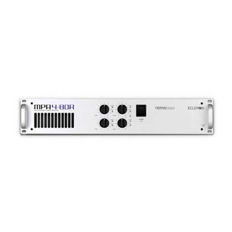
Summary of Contents for Ecler MPA4-80R
- Page 1 MPA4-80R SERVICE MANUAL...
- Page 2 SERVICE MANUAL MPA4-80R INDEX - BLOCK DIAGRAM - SCHEMATICS - COMPONENTS LOCATION SCHEMA - TESTING AND QUALITY CONTROL - TECHNICAL CHARACTERISTICS - WIRING DIAGRAM - CONFIGURATION DIAGRAM - MECHANICAL DIAGRAM - PACKING DIAGRAM...
- Page 3 J. Colomines 060613 EP04-06 MPA4-80R ECLER drawn: date: project: product: approved: BLOCK DIAGRAM title: 10.0744 01.00 A.S. number: version:...
- Page 11 22k1 R105 FCXR14332000 33k2 R106 FCXR14100000 10k0 R107 FCXR14182000 18k2 R108 FCXR11200000 20.0 R109 FCXR11200000 20.0 R110 FCXR11200000 20.0 R111 FCT803010000 Screw M3x10 SPA SC100 FCARM3201000 Metal Washer 3. WA100 FCARAT000000 Washer insulant WA101 40-0173-0100 EP04-06 MPA4-80R.xls 1 of 1...
- Page 14 BC857B Q104 FCXTT0857000 BC857B Q107 FCXTT0857000 BC857B Q108 FCXTT0857000 BC857B Q109 FCXTT0857000 BC857B Q110 FCTR15030000 MJE15030 Q113 FCTR15031000 MJE15031 Q114 FCRP54680000 6k8/2 PR02 R201 FCRP54680000 6k8/2 PR02 R202 FCXR53237000 2k37 R264 FCXR53237000 2k37 R265 40-0173-0100 EP04-06 MPA4-80R.xls 1 of 2...
- Page 15 FCARDE030000 Toothed Washer f/M3 WA102 FCARDE040000 Toothed Washer f/M4 WA103 FC4I00545000 1005.04.50 WI101 FC0C01215000 1012.01.50 WI102 FC0E01938000 1019.03.80 WI111 FC0E01945000 1019.04.50 WI112 FC0E01931000 1019.03.10 WI113 FC0E01945000 1019.04.50 WI114 FC2F01750000 1017.05.00 WI117 FC2F01650000 1016.05.00 WI118 40-0173-0100 EP04-06 MPA4-80R.xls 2 of 2...
- Page 18 C145 FCCDK1470000 C470n C146 FCCE30001000 1u/63 C147 FCCE30001000 1u/63 C148 FCCE30001000 1u/63 C149 FCCE30001000 1u/63 C150 FCXCD2470000 470p C151 FCXCD2470000 470p C152 FCXCD2470000 470p C153 FCXCD2470000 470p C154 FCCE25010000 10u/50 C155 FCXCD4100000 100n C156 40-0173-0100 EP04-06 MPA4-80R.xls 1 of 5...
- Page 19 IC106 FCIC07201000 TL072 IC107 FCIC07201000 TL072 IC108 FCIC07201000 TL072 IC109 FCIC07201000 TL072 IC110 FCBASJ020000 YKB21-5009 J101 FCBASJ020000 YKB21-5009 J102 FCCTM0005000 B5B-EH-A J103 FCBASX090000 YKF52-5005 J104 FCBASX090000 YKF52-5005 J105 FCBASX090000 YKF52-5005 J106 FCBASX090000 YKF52-5005 J107 40-0173-0100 EP04-06 MPA4-80R.xls 2 of 5...
- Page 20 24k3 0.5% R122 FCXR64243000 24k3 0.5% R123 FCXR64243000 24k3 0.5% R124 FCXR64243000 24k3 0.5% R125 FCXR64243000 24k3 0.5% R126 FCXR64243000 24k3 0.5% R127 FCXR64243000 24k3 0.5% R128 FCXR64243000 24k3 0.5% R129 FCXR64243000 24k3 0.5% R130 40-0173-0100 EP04-06 MPA4-80R.xls 3 of 5...
- Page 21 FCXR54237000 23k7 R175 FCXR54237000 23k7 R176 FCXR52562000 R177 FCXR52100000 100.0 R178 FCXR54237000 23k7 R179 FCXR54237000 23k7 R180 FCXR52562000 R181 FCXR52100000 100.0 R182 FCXR54100000 10k0 R183 FCXR54237000 23k7 R184 FCXR54237000 23k7 R185 FCXR54237000 23k7 R186 40-0173-0100 EP04-06 MPA4-80R.xls 4 of 5...
- Page 22 S103 FCINTAP13000 8019L S104 FCINTAP14000 8021L S105 FCINTAP14000 8021L S106 FC4K00710000 1007.01.00 WI101 FC4G00415000 1004.01.50 WI102 FC4G00425000 1004.02.50 WI103 FC4G00415000 1004.01.50 WI104 FC4G00425000 1004.02.50 WI105 FC4L00812000 1008.01.20 WI107 FC4K00710000 1007.01.00 WI108 FC4N04940000 1049.04.00 WI111 40-0173-0100 EP04-06 MPA4-80R.xls 5 of 5...
-
Page 23: Verification Process
11. Connect the amplifier's mains plug to a variac outlet, and leave its output down to 0 volts. SWITCH POSITIONS: SWITCH POSITION IN1/IN1+IN2 IN2/LINK CH1 LINK CH1 STEREO / BRIDGE STEREO IN3/LINK CH1 LINK CH1 IN4/LINK CH2 LINK CH2 STEREO / BRIDGE STEREO 51-0191-0100 EP04-06 MPA4-80R Anglès.doc 1 of 4... - Page 24 25. At this point, all clip indicators should be lighting. If necessary, add a little bit of level to the input signal. 26. Set the IN1/IN1+IN2 selector to IN1+IN2, and verify that the output signal level drops 6dB on all outputs. 27. Return the switch back to IN1. 51-0191-0100 EP04-06 MPA4-80R Anglès.doc 2 of 4...
- Page 25 Ground continuity test: Connect the tester’s probes between the mains ground contact and the unit’s backside main ground test point. When applying a 10A current, verify that the ground impedance is lower than 0.1Ω. 51-0191-0100 EP04-06 MPA4-80R Anglès.doc 3 of 4...
-
Page 26: Quality Control
All mechanical parts should be visually revised, in order to detect scratches on the unit's painting; all screws should be on their place, correctly tight and unmarked. Check out the unit's general presentation. 51-0191-0100 EP04-06 MPA4-80R Anglès.doc 4 of 4... -
Page 27: Technical Characteristics
±10V/µs * Channel crosstalk @ 1kHz >60dB Input Sensitivity / Impedance 0dBV/>20kΩ Mains Voltage See characteristics in the back of the unit. Power consumption (max. Out) 524VA Dimensions 482.6x88x391mm Weight 9.5kg * VCA OFF 53-0082-0100 EP04-06 MPA4-80R.doc 1 of 1... - Page 28 3x Heat Shrink 16.1086.01.00 16.1087.01.00 16.1004.01.50 16.1012.01.50 16.1005.04.50 16.1004.02.50 16.1007.01.00 16.1008.01.20 WARNING: WIRES SEPARATED FROM RADIATOR 16.1007.01.00 16.1049.04.00...
- Page 30 SCREW M8 TRANSFORMER 1 GENERIC TRANSFORMER TOOTHED WASHER M8 1 GENERIC TRANSFORMER NUT M8 DETAIL A TO FIX POWER AMP MODULES USE SCREWS FCT400290900 Jordi Folch 070309 EP04-06 MPA4-80R ECLER drawn: date: project: product: approved: title: MECHANICAL DIAGRAM 30.0225 01.01...
- Page 31 1 FCCONX017600 MAINS CORD 3x1,5 ST EU 1 FCETI0951140 PRODUCT LABEL PACK (ONE FOR EACH UNIT) 1 FCFUNMAN0000 USER MANUAL BAG 1 FCMANMPA7300 USER MANUAL MPA4-80R 6-80R 12 4 FCPIE1125500 RUBBER FOOT 4 FCREG1006000 CONNECTING TERMINAL STRIPS 2C 4 FCREG1007000 CONNECTING TERMINAL STRIPS 3C...


Need help?
Do you have a question about the MPA4-80R and is the answer not in the manual?
Questions and answers