Table of Contents
Advertisement
Advertisement
Table of Contents

Subscribe to Our Youtube Channel
Related Manuals for Giada AP23


Summary of Contents for Giada AP23
- Page 2 Statement The copyright of this manual belongs to Shenzhen JEHE Technology Development Co., Ltd. (Giada, JEHE’s global brand) and all rights are reserved. The company reserves the right to change this manual at any time without notification. Specifications here are for reference only, please take the real product as standard.
-
Page 3: Table Of Contents
Table of Contents 1. Product Introduction ..................... 4 1.1 Brief Introduction ....................4 1.2 Motherboard Picture ................... 4 1.3 Specification ....................... 5 2. Hardware Usage Instruction.................. 6 2.1 Dimensions chart ....................6 2.2 Interface Definition ..................... 6 2.2.1 Interface Diagram ..................6 2.2.2 Interface Definition ................... - Page 4 3.2.6 CPU Configuration .................. 22 3.2.6.1 CPU Power Management .............. 23 3.2.7 AMI Graphic Output Protocol Policy ............24 3.2.8 Network Stack Configuration ..............25 3.2.9 CSM Configuration .................. 27 3.3 Chipset ....................... 28 3.3.1 North Bridge ..................... 29 3.3.2 South Bridge ..................... 30 3.3.3 South Cluster Configuration ..............
-
Page 5: Product Introduction
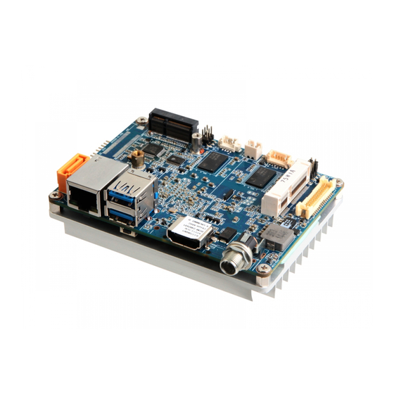
1. Product Introduction 1.1 Brief Introduction ® Giada AP23 adopts Intel Apollo Lake processor as well as onboard 2GB memory. It supports HDMI (Or VGA) and LVDS display output. With industrial grade design, the motherboard is suitable to be applied in Kiosk, Self terminal, network Security, POS etc. -
Page 6: Specification
1.3 Specification Intel ® Celeron N3350 Intel® Atom x5-E3930 1.10GHz (Up to 2.40GHz) Processor Frequency 1.30GHz (Up to 1.80GHz) BIOS AMI Source Code Chipset Type 2GB DDR3L-1600MHz Memory Socket Onboard Intel ® HD Graphics 500 Graphics Graphic Engine DirectX 11.1, OpenGL 3.0, OCL 1.1, OpenGL ES 2.0 Controller 1 x I210-IT Gigabit Ethernet Network... -
Page 7: Hardware Usage Instruction
2. Hardware Usage Instruction 2.1 Dimensions chart 2.2 Interface Definition 2.2.1 Interface Diagram - 6 -... -
Page 8: Interface Definition
2.2.2 Interface Definition Name Function PIN Definition Front Panel F_PL Front COM F_COM1 Front COM F_COM2 - 7 -... - Page 9 GPIO GPIO Pin Front_USB F_USB SATA_ SATA Power Supply Pin INVT Inverter Pin - 8 -...
- Page 10 LVDS_ LVDS_PWR_ PWR_ SEL Pin LVDS LVDS Pin I_SATA1 SATA3 - 9 -...
-
Page 11: Accessories Installation Steps
2.3 Accessories Installation Steps For safety reasons, please ensure that the board is disconnected with power before installation. 2.3.1 MSATA Installation 1. Plug the MSATA module into the mini PCIE slot. 2. Secure the module to the carrier by tightening up the screw. - 10 -... -
Page 12: Wifi (M.2) Installation
2.3.2 WIFI (M.2) Installation 1. Plug the WIFI (M.2) into the appropriate slot. 2. Secure the module to the carrier by tightening up the screw. - 11 -... -
Page 13: Bios Setup
The descriptions relating to BIOS setup in this Manual is for reference only since the BIOS version of the product might be upgraded. Giada provides no guarantee that all the contents in this Manual are consistent with the information you acquired. - Page 14 B. Function Keys definitions Hot Key Description ↑ (Up key) Move to the previous item ↓ (Down key) Move to the next item ← (Left key) Move to the left item → (Right key) Move to the right item Exit the current interface Page Up Change the setup state, or add the values Page Down...
- Page 15 (Fig 1) 1) Main (standard CMOS setup) This item is used for setting the date and time. 2) Advanced (advanced BIOS setup) This item is used for setting the advanced functions provided by BIOS, such as specifications of PCIe facilities, CPU, HDD, etc. 3) Chipset 4) Security (set the administrator/user password) 5) Boot (startup configuration characteristics)
-
Page 16: Main (Standard Cmos Setting)
3.1 Main (Standard CMOS setting) 1) System time (hh:mm:ss) Use this item to set the time for the computer, with the format as “HH / MM / SS”. 2) System date (mm:dd:yy) Use this item to set the date for the computer, with the format as “week, MM / DD / YY”. - 15 -... -
Page 17: Advanced (Advanced Bios Setup)
3.2 Advanced (Advanced BIOS setup) 3.2.1 Driver Health Provide Health Status for the Drivers/Controllers - 16 -... -
Page 18: Lvds Configuration
3.2.2 LVDS Configuration If the item is enable, user can select different resolutions. - 17 -... -
Page 19: F81801 Super Io Configuration
Disable If the item is enabled, user can select different resolutions. Normally, the default resolution is 1920_1080_8. If user need other resolutions, Select LVDS Mode please contact Giada FAE (email:support@giadatech.com) for customized resolution. 3.2.3 F81801 Super IO Configuration The menu... -
Page 20: Serial Port 1 Configuration
3.2.3.1 Serial Port 1 Configuration Options Description Serial Port 1 Configuration The serial port is enabled by default. Serial Port Enabled Disabled. User can set the serial port by change settings option. Auto IO=3F8H ; IRQ=4 ; IO=3F8H ;... -
Page 21: Hardware Monitor
Options Description The serial mode is RS232 by default. RS232 Serial Mode RS485 RS422 3.2.4 Hardware monitor Options Description PC Health Status PC Health Status PC Health Status. CPU temperature CPU Current Temperature. - 20 -... -
Page 22: Wake Configuration
3.2.5 Wake Configuration Options Description Wake Configuration Control Unit (MCU) and software (JAHC Technology Manager). JAHC Switch Disabled: The JAHC is disable by default. Enabled. The user can set up automatic startup by Fixed Time Wake system from RTC Enabled. -
Page 23: Cpu Configuration
3.2.6 CPU Configuration The menu Description CPU Configuration Socket 0 CPU Information Processor Base Frequency This item can show CPU’s CPU Power Management The user can set the C-State and TDP by Power Management. Intel Virtualization Technology is enabled by default. User can Intel Virtualization Technology enable and disable the Intel Virtualization Technology function. -
Page 24: Cpu Power Management
The menu Description The user can set the CPU P-States by P-STATE Coordination. HW_ALL. Enable hardware to support P-STATES. This item is enabled by default. P-STATE Coordination SW_ALL. Enable software to support P-STATES SW_ANY. Disabled P-STATE Function. This item is CPU digital thermal sensor. -
Page 25: Ami Graphic Output Protocol Policy
Options Description The user can enable and disable C State. C-states Enabled. This item is enabled by default. Disabled. The user can set power limit by power limit 1. Power Limit 1 Enable Enabled. This item is enabled by default. ... -
Page 26: Network Stack Configuration
3.2.8 Network Stack Configuration - 25 -... - Page 27 Options Description Network Stack Configuration Network Stack This item can enable and disable UEFI network stack. The user can enable or disable IPV4 PXE Boot support. If disabled IPV4 PXE boot option will not be created. Ipv4 PXE Support Enabled.
-
Page 28: Csm Configuration
3.2.9 CSM Configuration Options Description CSM Configuration Enabled. This item is enabled by default. CSM Support Disabled. This item is used for controlling the execution of Legacy network state. Do not launch. The network stack is do not launch by default. Network ... -
Page 29: Chipset
Options Description Determines OpROM execution policy for devices other than Network, storage or video Do not launch. Other PCI devices UEFI. It means only support UEFI mode boot. Legacy. It means only support legacy mode boot. The other PCI devices is legacy by default. -
Page 30: North Bridge
3.3.1 North Bridge Options Description North Bridge Configuration Maximum value of TOLUD(Top of Low Usable Dram) for GPU Max TOLUD 3 GB. The value TOLUD is 3GB by default. Enable/Disable above 4GB MemoryMappedIO BIOS assignment. This is disabled automatically when aperture size is set to Above 4GB MMIO BIOS 2048MB assignment... -
Page 31: South Bridge
3.3.2 South Bridge Options Description South Bridge Configuration This item can set serial IRQ. Serial IRQ Mode Continuous. This item is continuous by default. Quiet. Enabled. This item is enabled by default. SMBus Support Disabled. The user can set the target OS(Android or windows) as needs. OS Selection ... -
Page 32: South Cluster Configuration
3.3.3 South Cluster Configuration - 31 -... - Page 33 Options Description SATA Drivers Configuration This item can enable or disable the chipset SATA controller. The Chipset SATA chipset SATA controller supports the 2 black internal SATA ports (up to 3Gb/s supported per port). The user can determine how SATA controller(s) operate. It can SATA Mode Selection support AHCI and RAD mode.
-
Page 34: Security Setup (Set The Administrator/User Password)
Security Setup (set the administrator/user password) 3.3.4 If this function is selected, the following information will appear: Enter New Password hhhhhh Then enter a password which is no more than eight characters and press <Enter>. BIOS will require to enter the password again. Once you enter it again, BIOS will save the set password. -
Page 35: Boot Menu
3.4 Boot Menu Boot Item Description Boot Configuration This item is use to set the wait time of entering the operation system. During the BIOS post, if user doesn't press the keyboard, Setup Prompt Timeout it won't respond unless you reboot the BIOS. The Setup Prompt Timeout is 3s by default. -
Page 36: Save&Exit
3.5 Save&Exit Save Exit Item Description Save Options Save Changes and Reset Save all changes and exit Discard Changes and Reset Give up the settings and exit. Restore Defaults Recover it to default. Boot Override Whole Boot devices - 35 -... -
Page 37: Jahc Introduction
4. JAHC Introduction JEHE Active Hardware Control (JAHC) management system includes both hardware Micro Control Unit (MCU) and software (JAHC Technology Manager). It can support following functions: 1. Automatically boot up when power on. It is controlled by the Micro Control Unit (MCU) chip. 2. - Page 38 b. Select Advanced- > Power configuration- > JAHC Enable- > Enabled. - 37 -...
-
Page 39: Jahc Software
Switch the JAHC button to “on” or enable it in BIOS if there is no physical button on the chassis. c. Supported operation system: Windows 10 64bit, Linux 64bit. How to install JAHC software: Please download the JAHC.EXE from Giada website: www.giadatech.com, then follow up below steps: - 38 -... - Page 40 a. Double-click the JAHC.EXE file, the setup wizard will pop up, select destination location and click [Next] button to continue the installation. b. Click [Next] button to continue the installation. - 39 -...
- Page 41 c. Select [Create a desktop shortcut] and click [Next] button. d. Click [Install] button to continue the installation. - 40 -...
- Page 42 e. Click [Finish] button to finish the installation. You can select [Launch JAHC] to run the software automatically after finishing the installation. Notice: The JAHC will be added into boot item when it is installed. It will start up when system boot - 41 -...
-
Page 43: Startup & Shutdown Time Setup
4.2.3 Startup & shutdown time setup After install the JAHC software, double click the JAHC icon on taskbar and the setup menu will pop One week as a circle, maximum 3 schedules per day. Select each schedule to set up the resume time and shutdown time. -
Page 44: Watchdog Api And Instruction
You can click [Delay] button and set up the time to delay the shutdown or click [Cancel] button to cancel the shutdown. 4.3 Watchdog API and instruction Please contact Giada FAE (email:support@giadatech.com) for watchdog API software and instruction. - 43 -... - Page 45 - 44 -...
Need help?
Do you have a question about the AP23 and is the answer not in the manual?
Questions and answers