Table of Contents
Advertisement
Advertisement
Table of Contents

Related Manuals for Giada N70E-DR


Summary of Contents for Giada N70E-DR
- Page 1 N70E-DR All right reserved...
-
Page 2: Acknowledgment
Dear Giada user, Thank you very much for choosing Giada server products. Giada server products are designed for enterprises and households and applied in lots of areas such as Data storage, Cloud computing, Video surveillance and Cloud storage. Providing server products with hi-performance and reliable quality is the service principle of Giada brand. -
Page 3: Attention
Attention Attention The following factors resulting in product failure or damage is not in the scope of free warranty: A. Damages caused by natural disaster ( flood, fire, earthquake, lightning, typhoon, etc. ), or any event of force majeure or man-made damage. B. -
Page 4: Table Of Contents
Catalog Catalog Acknowledgment ___________________________________________________________ 1 Copyright & Trademarks ______________________________________________________ 1 Attention __________________________________________________________________ 2 Catalog ___________________________________________________________________ 3 Chapter 1 Product Features ___________________________________________________ 4 1.1 Safety Information ____________________________________________________________ 4 1.2 Product Specifications _________________________________________________________ 5 1.3 Product Highlights ____________________________________________________________ 6 Chapter 2 Hardware Installation _______________________________________________ 7 2.1 Installation Precautions ________________________________________________________ 7 2.2 Motherboard Layout __________________________________________________________ 8 2.3 Installing the Memory _________________________________________________________ 9... -
Page 5: Chapter 1 Product Features
Product Features Chapter 1 Product Features 1.1 Safety Information 1.1.1 Safety of Electric A. To avoid damage of electric shock, please turn off the power and unplug the power cord before moving the computer. B. Before you add or remove any component or extended device, do turn off the power and unplug the power cord;... -
Page 6: Product Specifications
OS Support greater than 3G, Installer may fail if the target disk is larger than 3G, data disks did not ask Caution: Giada reserves the right to make any changes to the product specifications and product related information without prior notice. -
Page 7: Product Highlights
Product Features 1.3 Product Highlights Latest Processor Technology N70E series motherboard use the latest Intel® low-power processor. The power consumption is only 17W, but the performance remains good to meets all the date computing requirements. With the CPU on-board design, the cost of cooling will be reduced, and makes the system more stable and reliable. -
Page 8: Chapter 2 Hardware Installation
Hardware Installation Chapter 2 Hardware Installation 2.1 Installation Precautions The motherboard contains numerous delicate electronic circuits and components which can become damaged as a result of electrostatic discharge (ESD). Prior to installation, carefully read the user's manual and follow these procedures: A. -
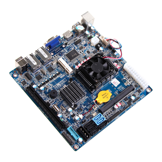
Page 9: Motherboard Layout
Hardware Installation 2.2 Motherboard Layout... -
Page 10: Installing The Memory
Hardware Installation 2.3 Installing the Memory Caution: a、Always turn off the computer and unplug the power cord from the power outlet before installing the memory to prevent hardware damage. b、Memory modules have a foolproof design. A memory module can be installed in only one direction. If you are unable to insert the memory, switch the direction. -
Page 11: Rear Panel Connectors
Hardware Installation 2.4 Rear Panel Connectors USB2.0 RJ45-2 Audio ports PS 2 / USB3.0 HDMI RJ45-1 1, USB2.0 ports The USB2.0 ports support USB2.0 specification. Use this port for USB devices such as a USB keyboard/mouse, USB printer, USB flash drive and etc. 2, PS/2 port PS/2 is used for connecting keyboard/mouse or other devices with PS/2 connector. -
Page 12: Internal Connectors
Hardware Installation 2.5 Internal Connectors Read the following guidelines before connecting external devices: A. First make sure your devices are compliant with the connectors you wish to connect. B. Before installing the devices, be sure to turn off the devices and your computer. Unplug the power cord from the power outlet to prevent damage to the devices. -
Page 13: Hardware Installation
Hardware Installation 2.5.1. JPF Jumper JPF allows you to enable or disable the Power Force On function. If enabled, the power will always stay on automatically. If this function is disabled (default setting), the user needs to press the power button to power on the system. Pin# Definitions Disable... - Page 14 Hardware Installation 2.5.3. CLR_CMOS Jumper CLR_CMOS is used to clear CMOS, Connect the two pins, the BIOS setting will be restored to the default setting. 2.5.4. USB prot Intelnal USB2.0 port, can be used to connect an USB device.
- Page 15 Hardware Installation 2.5.5. PCIE Slot PCIE in 16X physical interface, supports PCIE Gen2, running at 4X. 2.5.6. F_USB2.0 Front Panel USB 2.0 header, supports two USB2.0 ports. Pin# Definitions Pin# Definitions...
- Page 16 Hardware Installation USB DO- USB D1- USB DO+ USB D1+...
- Page 17 Hardware Installation 2.5.7. F_USB3.0 Front Panel USB 3.0 header, supports two USB3.0 ports. Pin# Definitions Pin# Definitions F-USB3.0 RXDN2 F-USB3.0 RXDP2 F-USB3.0 RXDN2 F-USB3.0 TXDP2 F-USB2.0 0_N2 F-USB2.0 0_P2 F_OCP F-USB2.0 0_P1 F-USB2.0 0_N1 F-USB3.0 TXDP1 F-USB3.0 TXDN1 F-USB3.0 TXDP1 F-USB3.0 TXDN1...
- Page 18 Hardware Installation 2.5.8. TPM Header TPM header is used to connect a Trusted Platform Module(TPM is a third party device can be plugged into this board providing protection for your PC, BIOS, OS and net connection, etc. ). Pin# Definitions Pin# Definitions FRAME...
- Page 19 Hardware Installation 2.5.9. SATA SATA0/1 support SATA3.0 technology, provide up to 6Gbps transmission speed; SATA2/3/4/5 support SATA2.0 technology, provide 3Gbps transmission speed. 2.5.10. ATX_1x4P Power Connector for Add-on devices. (Note: Do NOT plug the power supply cable into this socket) Pin# Definitions Pin#...
- Page 20 Hardware Installation 2.5.11. J6 Jumper J6 allows you to enable or disable the m-SATA port. m-SATA port and SATA port 3 use the same data transmission channel, this two ports can not work at the same time and you need to enable one and disable the other one. The default setting is enable m-SATA port and disable SATA port 3.
- Page 21 Hardware Installation 2.5.13. JD1 External Buzzer/Speaker/Power LED, Pins 1-3 (Power LED), Pins 4-7 (External Speaker). Pin# Definitions Pin# Definitions Power LED External Speaker Power LED External Speaker Power LED External Speaker External Speaker...
- Page 22 Hardware Installation 2.5.14. JOH The JOH header is used to connect a LED to provide warnings of chassis overheat. This LED will also blink to indicate a fan failure. Refer to the flloweing table for pin definitions. Pin# Definitions Signal 2.5.15.
- Page 23 Hardware Installation 2.5.16. ATX1(24PIN) ATX 24-Pin Power Connector. 2.5.17. Memory socket Memory socket, supprots DDR3 SODIMM, up to 8GB supported. 2.5.18. JWD1 Watch Dog Enable/Disable. Pin# Definitions Enable Disable 2.5.19. JPUSB1 Use JPUSB1 jumper to enable the function of "System Waking-Up via USB devices". This jumper allows you to "wake-up"...
- Page 24 Hardware Installation 2.5.20. CPU_FAN, SYS_FAN CPU Fan header and SYSTEM Fan header. Pin# Definitions Pin# Definitions +12V +12V Tachometer Tachometer PWM_Control PWM_Control 2.5.21. ATX2(4PIN) External Power Connector. Pin# Definitions Pin# Definitions 2.5.22. JP3, 4 Pin 1 DCD/5V Select for COM and COM2. Pin# Definitions...
- Page 25 Hardware Installation 2.5.23. COM2 Serial Port 2 Headers. Pin# Definitions Pin# Definitions Ground 2.5.24. m-SATA m-SATA port, you can intall a m-SATA storage device. Make sure you have enable the m-SATA port before you intall a SSD. Please refer to ”11.J6”.
-
Page 26: Chapter 3 Bios Setting
BIOS Setting Chapter 3 BIOS Setting BIOS (Basic Input and Output System) records hardware parameters of the system in the EFI on the motherboard. Its major functions include conducting the Power-On Self-Test (POST) during system startup, saving system parameters and loading operating system, etc. BIOS includes a BIOS Setup program thatallows the user to modify basic system configuration settings or to activate certain system features. -
Page 27: Bios Setting
BIOS Setting 3.1.2 Navigation The BIOS setup utility uses a key-based navigation system called hot keys. Most of the BIOS setup utility hot keys can be used at any time during the setup navigation process. These keys include <F1>, <F9>, <F10>, <Enter>, <Esc>, <Arrow>, <+>, <->, etc. The following are hot keys. -
Page 28: Main
BIOS Setting 3.2 Main When you first enter the BIOS Setup Utility, you will enter the Main setup screen. You can always return to the Main setup screen by selecting the Main tab. Caution: A. When the system is not stable as usual, select the Restore Defaults item to set your system to its defaults. B. -
Page 29: Advanced
BIOS Setting 3.2.2 System Information Use this menu to show System BIOS, CPU, Memory information and so on. 3.3 Advanced The Advanced menu shows the submenu options for configuring the function of various hardware components. Select a submenu item, then press Enter to access the related submenu screen. - Page 30 BIOS Setting 3.3.1 HDD Configuration SATA Device This item Enables or Disables the built-in SATA controllers on the motherboard. The default setting is [Enabled]. Interface Combination This item selects the SATA mode for a device installed on a SATA drive. The default setting is [AHCI].
- Page 31 BIOS Setting 3.3.2 Intel(R) Rapid Start Technology iRST Support Enable Intel Rapid Start Technology, default is Enabled. Entry on S3 RTC wake iRST invocation upon S3 RTC wake, default is Enabled. Entry after Enable RTC wake timer at S3 Entry.
- Page 32 Appendix 3.3.3 IGD Configuration This menu show Integrated Graphic Device option and related function settings. IGD – Boot Type Select the Video Device activated during POST, default is follow by VBIOS Setting. IGD – LCD Panel Type Select the Video Device activated during POST, default is follow by VBIOS Setting. Panel Color Depth Select the LFP Panel color depth.
-
Page 33: Hardware Monitor
BIOS Setting 3.3.4 Hardware Monitor This menu show system HWM information and related function settings. CPU Fan Control Mode Switch the CPU fan mode between Full Speed, Smart Mode and manually mode. CPU Temperature Limit of OFF The CPU fan will stop less then this temperature value. CPU Temperature Limit of Start The CPU fan will start higher than this temperature value. -
Page 34: Security
Appendix 3.4 Security The Security menu allows you to safeguard and protect the system from unauthorized use by setting up access passwords. There are two types of passwords that you can set: Set Supervisor Password Supervisor Hint String Entering this password will allow the user to access and change all settings in the Setup Utility. -
Page 35: Boot
BIOS Setting 3.5 Boot The Boot menu allows you to set the drive priority during system boot-up. You can use Up/Down Arrow key and “+”/“-“ to set the Boot driver Priority order. -
Page 36: Save And Exit
Appendix 3.6 Save and Exit The Exit menu displays the various options to quit from the BIOS Setup. Highlight any of the exit options then press Enter. Exit Saving Changes Saves changes, then exit the BIOS setup. Exit Discarding Changes Do not save changes, and then exit the BIOS setup. -
Page 37: Chapter 4 Appendix
"end of life" product. Restriction of Hazardous Substances (RoHS) Directive Statement Giada products have not intended to add and safe from hazardous substances (Cd, Pb, Hg, Cr+6, PBDE and PBB). The parts and components have been carefully selected to meet RoHS requirement. - Page 38 SHENZHEN JEHE TECHNOLOGY DEVELOPMENT CO.,LTD ADD: 2/F, Block A, Tsinghua Information Harbor, North Section, Shenzhen Hi-tech Park, Nanshan District, Shenzhen, China http://www. giadatech. com...
Need help?
Do you have a question about the N70E-DR and is the answer not in the manual?
Questions and answers