
Related Manuals for Giada MI-D525


Summary of Contents for Giada MI-D525
- Page 1 Motherboard User’s Manual www.giadatech.com MI-D525 Version 001 All right reserved...
-
Page 2: Table Of Contents
www.giadatech.com Contents Gratitude …………………………………………………………………………… III. BIOS setting …………………………………………………………………… 1. Main menu ………………………………………………………………… I. About the product ……………………………………………………………… 2. Main (standard CMOS setup) …………………………………………… 1. Picture of the motherboard ……………………………………………… 3. Advanced (Advanced BIOS setup) ……………………………………… 2. Features …………………………………………………………………… 4. Boot Configuration ………………………………………………………… 2.1 Processor ………………………………………………………………... -
Page 3: Gratitude
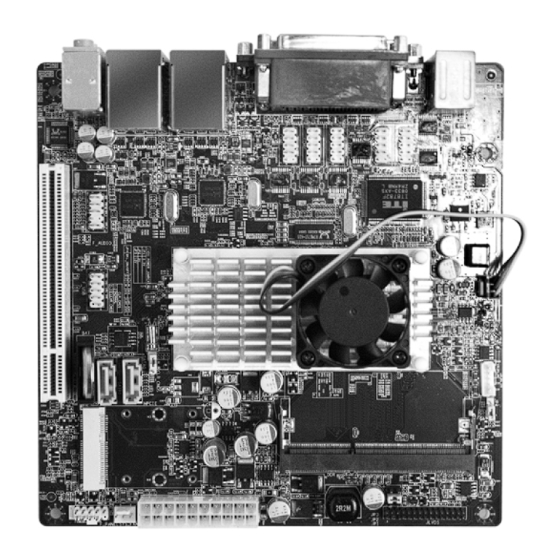
It supports DDR3 800 Dual-channel memory, on-board HD-AUDIO sound card. Support USB2.0. Any question about the product, please send e-mail to our support center. Headquarter: Sales@giadatech.com support@giadatech.com USA office: support@giadapc.com NOTE: This is Giada real product photo show for your reference only, Product appearance depends on goods. -
Page 4: Features
www.giadatech.com II. Hardware installation Warning 2. Features 2.1 Processor The motherboard consists of a great number of ICs and other components. · On-board Dual-core Intel® Atom™ processor D525 These ICs might be damaged by the static charge. Therefore, the user must ·... -
Page 5: Layout Of Motherboard
www.giadatech.com 1. Layout of motherboard 2. Installing memory Please install the memory in accordance with the following procedures: · Align the golden finger of the memory to the groove of the interface slot and pay attention the concave hole of golden finger should be aligned to the convex point of the slot. -
Page 6: Sata1/Sata2 (Serial Ata Flat-Cable Sockets)
www.giadatech.com 3.1. SATA1/SATA2 (Serial ATA flat-cable sockets) 3.3.CLR_CMOS(CMOS pin). Serial ATA sockets can reach a transmission speed of 300MB/s, and you can The correct time, system hardware and other information are saved in the connect your Serial ATA device to this socket. CMOS memory of the motherboard. -
Page 7: F_ Audio(Pins For Front-End Audio Adapter)
www.giadatech.com Definition Definition Definition Definition USB D0- USB D1- MIC-BIAS USB D0+ USB D1+ OUT-R NULL NULL NULL OUT-L 3.6. ATX 12V (12V Power receptacle) 3.5. F_ AUDIO(Pins for front-end audio adapter) These audio adapter ports allow you to connect to the wire harness of the These audio adapter ports allow you to connect to the wire harness of the audio adapter. -
Page 8: F_ Panel (Front-End Control Panel)
www.giadatech.com Definition Definition Definition Definition 3.3V 3.3V HDLED+ PLED+ 3.3V -12V HDLED- PLED- PW_LED+ PS-ON RST+ PWRBTN RST+ 5VSB 3.7. F_ PANEL (Front-end control panel) This socket is used to connect the flat cables on the front-end panel. -
Page 9: Rear Panel Interface
Note The descriptions relating to BIOS in this Manual can only be used for reference as the BIOS version of the motherboard is upgraded continuously. Giada provides no guarantee that the contents in this Manual be consistent with the information you acquire. -
Page 10: Main Menu
www.giadatech.com To enter BIOS, you can press F1; to load the default values and enter the system, 1. Main menu you can press F2. After the self-detection process is completed, you can press When the system enters the CMOS Setup menu, you can see the main menu on DEL to enter the BIOS interface if no error is found. -
Page 11: Main (Standard Cmos Setup)
www.giadatech.com · Boot (startup configuration characteristics) 3. Advanced (Advanced BIOS setup) · Security (setting the administrator/user password) · Exit (option of exit) This item includes load optimal defaults/load failsafe defaults value/discard changes/ discard changes and exit. 2. Main (standard CMOS setup) Fig 3.3 4. -
Page 12: Security Setup
www.giadatech.com Quick Boot Interrupt 19 Capture [Disabled] If this item is set as Enabled, the system can be started within five seconds and If you use some PCI extension cards with built-in firmware program (like SCSI some detection items will be ignored. The options are [Disabled] and [Enabled]. extension card) and you want to start the system through Interrupt 19, you can set this item as [Enabled]. -
Page 13: Exit
www.giadatech.com If this function is selected, the following information will appear: 6. Exit Enter New Password hhhhhh Then, enter the password with not more than eight characters and press <Enter>. BIOS will requires to enter the password again. Once you enter it again, BIOS will save the set password. -
Page 14: Software Installation
www.giadatech.com IV. Software installation In Fig 4.1, click "Driver ", another UI appears as shown in Fig 4.2. NOTE:Pictures below just showing the driver install steps, please see the real product for detailed information. 1. Install driver for motherboard After you complete the installation of the operating system, you should then install the driver for the motherboard. -
Page 15: Install Driver For Chipset
www.giadatech.com 1.1. Installing driver for Chipset 1.2 Install Sound card driver After you click “Install” behind the “Intel Chipset driver” in the interface After you click “Install” behind the “Realtek HD audio driver” in the interface of Fig. 4.2, a dialog box as shown in Fig. 4.3 will pop up. Then you can of Fig. - Page 16 www.giadatech.com 1.3 Installing driver for on-board LAN chip 1.4 Installing driver for graphic card After you click “Install” behind the “Realtek 10/100/1000 LAN Driver” in the To install the driver for graphic card, you can click “Install” behind “XXX VGA interface of Fig.
- Page 17 www.giadatech.com After the initial installation of the driver, the default state of microphone is · For Windows Vista: mute. You need to turn it on manually, as shown in Fig. 4.7 and 4.8. After the driver for the audio adapter is stalled, you can click the Audio Manager at the lower right corner.
- Page 18 www.giadatech.com Click OK, and the controlling interface will turn to one shown in Fig. 4.12. Fig. 4.10 Click the right upper part of the control interface—Advanced Setup for Device, the interface shown in Fig. 4.12 will pop up. Then select Fig.
- Page 19 www.giadatech.com If you need to set the output of multi-channel, you should right click the Select Redistribution of Connectors. Then an interface will pop up, as shown in Fig. 4.14. After that, set the corresponding output. mouse at the corresponding output interface. A dialog box will pop up, as shown in Fig.
- Page 20 www.giadatech.com Changes or modifications not expressly approved by the party responsible for compliance could void the user's authority to operate the equipment NOTE: This equipment has been tested and found to comply with the limits for a Class B digital device, pursuant to Part 15 of the FCC Rules. These limits are designed to provide reasonable protection against harmful interference in a residential installation.
Need help?
Do you have a question about the MI-D525 and is the answer not in the manual?
Questions and answers