Table of Contents
Advertisement
Quick Links
Advertisement
Table of Contents

Subscribe to Our Youtube Channel
Related Manuals for Essilor ALM700


Summary of Contents for Essilor ALM700
- Page 1 Maintenance manual Auto Lensmeter ALM700...
-
Page 2: Table Of Contents
Light projecting unit assy......................13 5.10. Light receiving unit assy..................... 13 5.11. Marketing / Retention latch ....................14 5.12. Front cover ..........................14 5.13. PD plate assy. ALM700 ....................... 15 5.14. Nose pad assy........................15 5.15. LP lever ..........................15... -
Page 3: External Diagram
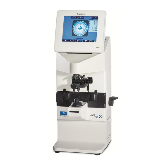
1. External diagram Utility box Utility box cover Top cover Back cover PD plate assy. Nose pad assy. Light receiving unit LP lever cover Front cover Printer cover unit Power supply inlet Power supply switch... -
Page 4: Exploded Diagram
Light projecting unit assy. Control board assy. Mechanical Marketing / Retention unit assy. unit Assy. Marking / retention latch PD plate assy. (ALM700) Nose pad assy. LP lever Light receiving unit assy. Switching power supply Printer Terminal unit assy. assy. -
Page 5: Wiring Diagram
UV light board assy. CN504 CN503 LCD assy. Brown To RS-232C 1/ 2/ 3 Control board assy. (only for ALM700 Brown / Red / Orange To CN6 Terminal unit assy. Printer control board assy. 2 / 3 / 5 RS-232C... -
Page 6: Assembly And Disassembly Of External Facing
4. Assembly and disassembly of external facing Turn off the power and unplug the power cord before disassembling the device. 4.1. Removal of back cover 1) Remove the LP lever and printer cover. The screw fixing the LP lever is placed under the screw hiding (refer to ‘5-15 LP Lever’). -
Page 7: Removal Of Lcd Assy
4.2. Removal of LCD assy 1) Remove 2 harnesses connected to the control board Assy. LCD assy. from the LCD Assy. (CN4 and 5: flat cables): Fig. 1 * CN5 has the lock function of the harness. Remove the harness from the control board Assy. by unlocking it. Control board assy. -
Page 8: Replacement Of Parts
5. Replacement of parts 5.1. Control board assy. 1) Remove the back cover. (Refer to ‘4. Assembly and Disassembly of External Facing’.) 2) Remove all of the connectors connected to the board. (Refer to ‘3. Wiring Diagram’.) 3) Unscrew the screws (cross-recessed bind screw M3×5) and spacers (resin) fixing the board. -
Page 9: Lcd Assy
Remove and replace the LCD BKT in the manner of 2). In case of ALM700, LCD top cover/ protection plate/ operation switch board Assy. cannot be replaced because it is touch panel. It can be replaced as LCD unit. -
Page 10: Switching Power Supply
Match the switch position and coordinates of touch panel. Touch There are 4 areas to touch in order. It is completed after touching 4 areas. (After adjustment) > 5.4. Switching power supply Remove the back cover. (Refer to ‘4. Assembly and Disassembly of External Facing’.) Disconnect the harnesses connected to the switching power supply. -
Page 11: Power Supply Switch
5.6. Power supply switch Remove the back cover. 2 clicks : top and bottom (Refer to ‘4. Assembly and Disassembly of External Facing’.) Remove the terminal unit Assy. by unscrewing 2 screws (cross- recessed bind screw M3×5) fixing the Assy. (※Do not disconnect the harnesses.): Fig. -
Page 12: Marking Pen, Retention Pin, Marking / Retention Unit Assy
5.8. Marking pen, retention pin, marking / Retention unit assy. Replacement of marking/ retention unit Assy. Removal Unscrew 2 screws (cross recessed binding screw M3×10 black) fixing the marking/ retention unit Assy. Installation Install the marking/retention unit Assy. so that the lens retention pin is positioned roughly in the center of the light receiving unit.: Fig. -
Page 13: Light Projecting Unit Assy
:Fig. 3 φ6) Lens stand aperture ( Scribing line Perforated screen φ13 ALM700: Perforated screen Light receiving unit assy. 5.10. Light receiving unit assy. Remove the light receiving unit cover. Light receiving unit assy. -
Page 14: Marketing / Retention Latch
5.11. Marketing / Retention latch Marking/Retention latch Remove the back cover. (Refer to ‘4. Assembly and Disassembly of External Facing’.) Remove the spring holding the marking/ retention unit Assy. :① Unscrew 2 screws (cross-recessed bind screw M3×5) fixing the plate which the marking/ retention latch is mounted. :② Hold both sides of the marking/ retention latch, and remove it to the direction of arrow. -
Page 15: Pd Plate Assy. Alm700
PD plate assy. ALM700 Remove the back cover (Refer to ‘4. Assembly and Disassembly of External Facing’.) Disconnect the harness of the control board which is connected to the PD Assy. (Only for ALM700, control board side: CN11) Remove the marking/ retention unit Assy. - Page 16 6. Troubleshooting 6.1. Type Display Condition Error Content Any measurement value is more than ‘±0.25’ when power is turned ・In case that the lens is set when power is turned on. Initial Error ・Measurement abnormality because of dust or unnecessary light etc.
- Page 17 6.2. Error handing procedure 1) “Initial error” In case that any measurement value (SPH, CYL or Prism) is more than ‘±0.25’ when the power is turned In case that the measurement image is abnormal when the power is turned on. «...
- Page 18 3) “Printer empty opened” In case that the printer cover is opened. « Printer Cover Opened» is displayed Printer cover is set correctly. Set the cover correctly, and cycle the power. Replace printer assy. « Printer Cover Opened » is still Normal displayed.
- Page 19 5) “EEPROM failure” In case that the control board has a abnormality when the power is turned on. « EEPROM Failure» is displayed “EEPROM Failure” is still Normal displayed even after cycling power Replace control . board 6) “Sensor error” In case that the light receiving unit Assy.
- Page 20 8) “Measurement error” In case that the light receiving unit of the device is exposed to the direct sunlight or strong light, or the lens under the lens stand is dirty or scratched. Also it may be displayed if the lens to be measured is dirty or scratched. «...
- Page 21 10) Others Symptom: it has no response (measurement values are not displayed) by moving the nose pad even though “PD Measure” is set as “On” on the setup screen and PD is displayed on the measurement screen. The symptom is improved after cycling power Normal *Check the harnesses before replacing the...
- Page 22 7. Evaluation of measurement image 7.1. How to enter dealer In case of ALM700 Turn on the device and hold the Memory/Add switch after the pilot lamp on the bottom right is on (right before the logo is displayed) until the comment as shown below appears.
- Page 23 7.3. Example of measurement image Normal The measurement image as shown on the left is displayed device normal measurement is taken correctly. Abnormal In case that the unnecessary light is entered, Background is uneven Measurement values varies ‘Measurement Error’ is displayed. In case that the lens to be measured is dirty or scratched or the lens under the lens holder is dirty.
- Page 24 7.4. Checking procedure of measurement image 1) Select “2. Freeze Image” with and display the measurement image with 2) The function switches are displayed by pressing the Memory/ Add switch after the measurement image is displayed. Name of Description of function function switch Displaying graph of vertical and horizontal brightness of measurement image.
- Page 25 Use the dedicated maintenance lens set when performing calibration. Perform the calibration in the dealer mode. In case of ALM700 Turn on the device and hold the Memory/Add switch after the pilot lamp on the bottom right is on (right before the logo is displayed) until the comment as shown below appears.
- Page 26 0.15 (standard value) Progressive lens judgment calibration value 2 InAT jud 0.18 (standard value) Calibration value of optical center of PD value (only for ALM700) PD 0mm 0.00 Calibration value of optical end of PD value (only for ALM700) 22.5...
- Page 27 1- Calibration procedure Follow the directions on the screen. Switch to the next screen from the first screen of “5. Calibration” by pressing Marking ok 2- 0D calibration All data are calibrated to OD automatically after a period of time (approx. 2 sec.). After approx 2 sec Marking ok Marking ok...
- Page 28 4- Calibration of Axis Input the test value with Place and align the cylindrical lens of +5D so that AXIS value becomes 90°. When the prisms reach between 0.00 and 0.01 in both X and Y directions, CYL and AXIS are automatically calibrated to the value of the test lens.
- Page 29 6- Adjustment of optical center of papillary distance (PD value) Remove the lens stand. Place the jig for adjusting PD center position against the PD plate as shown on the diagram (①). Place the jig for adjusting PD center position against the position against the nose pad (②).
- Page 30 8- Completion of calibration Calibration is completed. Now proceed to “28. Finished” by pressing . Switch to the menu screen by pressing . The calibration value is stored by switching to the menu screen. 9- Confirmation of calibration value Check if calibration is performed correctly by using the test lens used for the calibration. Open the MENU screen by pressing on the measurement screen.
- Page 31 9. Cleaning 9.1. Main unit Wipe with a dry cloth in case that main unit case, LCD cover or operation panel is dirty. If it has a stain which is hard to remove, moisten a soft cloth with a thinned neutral cleanser and wipe it. Do not use a solvent such as thinner.
- Page 32 10. Change of software 10.1. Preparation PC: OS; Windows XP or later RS-232C cable: straight (9Pin) Rewriting software: ComUpdate.exe Software of lensmeter: ALM*** (model name) V*** (version) Ensure to check the software version of the lensmeter to be changed.) 【Example of RS 232C connection】 D-Sub 9pin (male) D-Sub 9pin (female) Lensmeter...
- Page 33 Setting of device *The baudrate (communication speed) of RS-232C can be changed by pressing the switches (3) to (5). The setting at the time of activating the program mode is 115200bps. Usually, it is not necessary to change this setting. Indication of «...
- Page 34 (About the COM port, only the ports existing in PC are displayed. If there is only one COM port, it is not necessary to set it because it is set automatically when ComUpdate is activated.) ④ Set “Product”, “Baudrate” and “Hyper” as shown below. Set as “ALM700” Select the COM port to be used by clicking the up/down...
- Page 35 The new software is activated by pressing the ADD/Memory switch after writing the software. The software version can be checked by outputting the calibration value on “1. Output Adjust” of “4. Memory” MENU screen after starting maintenance mode. ALM700 Software version...
Need help?
Do you have a question about the ALM700 and is the answer not in the manual?
Questions and answers