Table of Contents
Advertisement
Advertisement
Table of Contents

Related Manuals for Essilor CS550


Summary of Contents for Essilor CS550
- Page 1 User Manual www.essilor-instruments.com...
-
Page 2: Table Of Contents
> C SER MANUAL ONTENTS ONTENTS I. I NTRODUCTION 1. Outline of product 2. Classifications II. S AFETY INFORMATION 1. Introduction 2. Indications for use 3. Safety symbols 4. Environmental factors 5. Safety precautions III. F EATURES IV. N OTES FOR USING THE INSTRUMENT V. -
Page 3: Introduction
I. I NTRODUCTION... -
Page 4: Outline Of Product
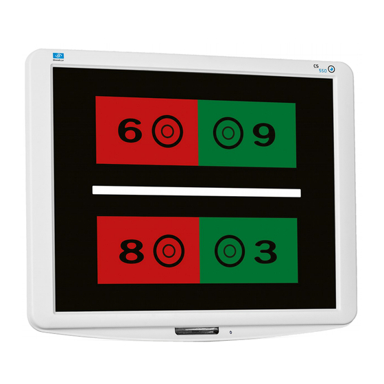
CS550 is an automatic visual acuity system, stand-alone type, which displays broad range of charts, based on LCD panel, including red /green for the eye optometry. The chart rotation for CS550 can be performed by either wired or wireless remote control or by external devices by control box of Digital Phoropter. -
Page 5: Safety Information
II. S AFETY INFORMATION... -
Page 6: Introduction
“Caution” indicates the presence of a hazard that could result in minor injury, or property damaged if ignored. This device is compliant with marking. Date of first marking: October 2015. 2. I NDICATIONS FOR USE The indications for use include the visual acuity for determining patient objective refraction. CS550 - Chart system > V1 - 10-2015... -
Page 7: Safety Symbols
• For more detailed information about disposal of your old appliance, please contact your city office, waste disposal service or the shop where you purchased the product CS550 - Chart system > V1 - 10-2015... -
Page 8: Environmental Factors
To avoid the risk of electric shock, this equipment must only be connected to supply mains with protective earth. CS550 shall be connected to the separate power supply as supplied by ESSILOR with Adapter Technology Co., Ltd, type ATM065-P120 Identified. - Page 9 SER MANUAL AFETY INFORMATION Do not placed the multiple socket-outlet for CS550 system on the floor in order to prevent liquid penetration and damage to the product. CS550 system shall not be connected with additional multiple socket-outlets or extension cords in addition to a designated single multiple socket-outlet.
-
Page 10: Safety Precautions
14.Before each operation, visually check the equipment for exterior mechanical damage(s) and for proper function. 15.Do not cover any ventilation grids or slits. 16.Immediately turn off and unplug any equipment that gives off smoke, sparks, strange noises or odors. CS550 - Chart system > V1 - 10-2015... -
Page 11: Features
III. F EATURES... - Page 12 0 to the 31 steps. It applies to all kinds of depth adjustment Red/Green chart. The Mirror function is added in CS550 system to let it installed at less Mirror function than 1.5m of narrow space and a user can easily select the function at his convenience.
-
Page 13: Notes For Using The Instrument
IV. N OTES FOR USING THE INSTRUMENT... - Page 14 4. Don't use organic solution such as alcohol, thinner, benzene, etc. to clean the surface of this instrument. It may damage the product. 5. Disconnect the power supply and consult the dealer when there is smoke, strange odors, or noise while working. CS550 - Chart system > V1 - 10-2015...
-
Page 15: Configuration
V. C ONFIGURATION... - Page 16 > V. C SER MANUAL ONFIGURATION CS550 is mainly consists of the components as below. Name Function 1: LCD display monitor Displayed the chart for test by using the graphic-processing function on computer 2: IR receive window Display chart to receive the infrared windows from remote controller...
- Page 17 Program sending button: display the programmed chart in sequence during operation Program reverse sending button: display the programmed chart right ahead Red/Green filter button: display the special chart adapted with Red/Green filter CS550 - Chart system > V1 - 10-2015...
- Page 18 > V. C SER MANUAL ONFIGURATION Mini USB socket: for operating CS550 and for charging the remote control battery LED: indicating the status of electric charge Loop part: connect the string with this part Battery housing 22-1 J6 connector removes...
-
Page 19: Installation
VI. I NSTALLATION... -
Page 20: Instruction For Wall Mounting
• Please put the product so that the center of the LCD screen is at the level of patient's eyes as this product is not affected by illumination. CS550 - Chart system > V1 - 10-2015... -
Page 21: Feature Set
DOWN: select this button, can move the key bottom or right. • ESC: go to selected features used in the previous step. • SEL (ENTER): feature of selecting and saving selected feature. CS550 - Chart system > V1 - 10-2015... -
Page 22: Feature Set Mode Disable
If the ESC key is selected two times, the save message will pop up. • If operator wants to save he has to push the SEL key and then change the initialized screen. CS550 - Chart system > V1 - 10-2015... - Page 23 If the ESC key is pressed two times, the save message will pop up. • If the operator wants to save he has to push the SEL key and then change the initialized screen. CS550 - Chart system > V1 - 10-2015...
- Page 24 If the operator wants to save he has to push the SEL key and then change the initialized screen. Color strength R/G filter adjustment function CS550 chart system provides 31steps of R/G filter density that can be used in accordance with test circumstances. All of Red/Green chart color charts can be reversed.
- Page 25 One more pressing the ESC button will show the short message asking whether the changes shall be saved or not. • For saving the new setting, press the SEL key and the screen is going to be changed to the initial setting mode. CS550 - Chart system > V1 - 10-2015...
- Page 26 One more pressing the ESC button will show the short message asking whether the changes shall be saved or not. • For saving the new setting, press the SEL key and the screen is going to be changed to the initial setting mode. CS550 - Chart system > V1 - 10-2015...
- Page 27 Interface Interface: It is the mode for selecting the communication for system operation. Remote mode is set as a default. CS550 - Chart system > V1 - 10-2015...
- Page 28 When going back to the default screen for acuity chart, press Program A and press the arrow button (=>l, l<=), then the visual acuity charts which are saved in Program A shows in sequence. It is the same procedure for showing charts saved in Program B. CS550 - Chart system > V1 - 10-2015...
- Page 29 VII. T EST METHOD...
-
Page 30: Test Method
3 green lights. ⓒ Blending > If a patient saw 4 dots, binocular function would be normal. ⓓ Diplopia > If a patient saw 5 dots, he/she would have diplopia. CS550 - Chart system > V1 - 10-2015... - Page 31 And if the result were an axial heteropsia,glasses would be prescribed and if a refractive heteropsia, contact lenses prescribed. CS550 - Chart system > V1 - 10-2015...
- Page 32 Add B.U in a right eye and B.D in a hyperdisparity left eye until being no deviation. Add B.U in a left eye and B.D prism ⓓ Right eye's in a right eye until being no hyperdisparity deviation. CS550 - Chart system > V1 - 10-2015...
- Page 33 B.D in a left eye until eye's hyperphoria being no deviation. ⓓ Right eye's Add B.U in a left eye and hyperphoria / Left B.D prism in a right eye eye's hypophoria until being no deviation. CS550 - Chart system > V1 - 10-2015...
-
Page 34: Remote Control Function
VIII. R EMOTE CONTROL FUNCTION... -
Page 35: General Function
> VIII. R SER MANUAL EMOTE CONTROL FUNCTION 1. G ENERAL FUNCTION CS550 - Chart system > V1 - 10-2015... -
Page 36: Slide Function
> VIII. R SER MANUAL EMOTE CONTROL FUNCTION 2. S LIDE FUNCTION 1. Additional function can be selected after slide button press. 2. Charts can be changed for quality improvement without notice. CS550 - Chart system > V1 - 10-2015... -
Page 37: How To Recharge A Remote Control
IX. H OW TO RECHARGE A REMOTE CONTROL... - Page 38 > IX. H SER MANUAL OW TO RECHARGE A REMOTE CONTROL Remote control can be rechargeable by the USB adapter. Remote control can be also rechargeable by USB cable, connecting with laptop or desktop. CS550 - Chart system > V1 - 10-2015...
-
Page 39: Cleaning The Product
X. C LEANING THE PRODUCT... - Page 40 Use a soft cloth with 90% Isopropyl Alcohol to clean the product's screen and the unit. Cleaning of the product should be performed when its screen is contaminated or dust level is bad in visual. Do not use paper towels. CS550 - Chart system > V1 - 10-2015...
- Page 41 XI. T ROUBLESHOOTING GUIDE...
-
Page 42: Troubleshooting Guide
Plug shall be into power outlet. IR detector is dirty. Clean the IR detector. Product will not respond to remote control. Batteries in remote are dead. Replace the batteries in the remote. CS550 - Chart system > V1 - 10-2015... -
Page 43: Environmental Conditions
XII. E NVIRONMENTAL CONDITIONS... - Page 44 +10°C ~ +40°C Operation Humidity 30 à 85 % Atmospheric pressure 70 à 106 kPa Temperature -10°C ~ +55°C Transportation and storage Humidity 10 à 95 % Atmospheric pressure 50 à 106 kPa CS550 - Chart system > V1 - 10-2015...
-
Page 45: Specifications
XIII. S PECIFICATIONS... - Page 46 (Remote control) Mini USB cable for recharging the remote control, power adapter, power Standard accessories cable, wall mounting bracket, user manual Optional accessories Floor Stand, Red/Green Glasses, Digital Refractor Cable, Desk-top Stand CS550 - Chart system > V1 - 10-2015...
-
Page 47: Components List
XIV. C OMPONENTS LIST... -
Page 48: Standard Accessories
TANDARD ACCESSORIES Mini USB cable for recharging the remote control, power adapter, power cable, wall mounting bracket, user manual. 2. O PTIONAL ACCESSORIES Floor stand, Red/Green glasses, digital refractor cable, desktop stand. CS550 - Chart system > V1 - 10-2015... -
Page 49: Service Information
XV. S ERVICE INFORMATION... -
Page 50: Repair
Please refer to the name plate and let us have the following information: • Name of the instrument: CS550 • Serial number: characters indicated on the name plate • Detailed defects CS550 - Chart system > V1 - 10-2015... - Page 51 Essilor Instruments USA 8600 W. Catalpa Avenue, Suite 703 Chicago, IL 60656 Phone: 855.393.4647 Email: info@essilorinstrumentsusa.com www.essilorinstrumentsusa.com...
Need help?
Do you have a question about the CS550 and is the answer not in the manual?
Questions and answers