Table of Contents
Advertisement
Advertisement
Table of Contents

Related Manuals for Essilor ALM 700


Summary of Contents for Essilor ALM 700
- Page 1 User Guide Auto Lensmeter ALM 700 Version 2 April 2015 UMALM700...
-
Page 3: Introduction
Introduction This device is aims to measure S, C, A, prism refractive power, UV transmission and PD of the framed lens and contact lens. About This Manual Please read this manual thoroughly so that safe and effective operation is ensured. (1) The information contained in this manual is subject to change without notice. - Page 4 this product complies with applicable CE directives. Manufacturer Electrical and Electronical Waste – please contact your distributor to recycle this product This manual contains the information about basic operation, inspection and maintenance etc. of ALM700.
-
Page 5: Safety Consideration
Safety Consideration General Cautions It affects its measurement accuracy if fingerprints or dust etc. are on the optical components such as glass parts under the lens stand. Do not touch them with hands, and avoid dust. If fingerprints or dust are adhered on the optical parts such as a lens etc., wipe it gently with ... -
Page 6: Table Of Contents
Contents Introduction............................1 About This Manual ...........................1 Safety Consideration.........................3 1. Accessories.............................6 2. Device.............................7 2.1 General Descritpion of Device....................7 2.2 Parts Identification........................7 3. Instructions for Use........................9 3.1 Installation..........................9 3.2 Connection/ Wiring ........................10 3.3 Maintenance/ Inspection .......................10 3.4 Disposal..........................11 4. Measurement Screen........................12 4.1 Description of Measurement Screen..................12 4.2 Preparation for Measurement....................13 4.2.1 Device Setting .........................13 4.2.2 Setup (Device Setting) Screen ..................13... - Page 7 6.8.2 Measurement Procedure....................33 7. Marking ............................34 7.1 Lens without Astigmatism ....................34 7.2 Lens with Astigmatism ......................34 7.3 Marking of Prism Lens......................35 8. Other Functions ..........................36 8.1 Auto Memory Function......................36 8.1.1 Operation Procedure .......................36 8.2 Power Saving Function ......................37 9. Error Display..........................38 9.1 Type............................38 9.2 Error Handling Procedure.....................39 10.
-
Page 8: Accessories
1. Accessories Power cord: 1 Printer paper: 1 Operation manual: 1 (2.5m) (Width: 58mm) Dust cover: 1 Contact lens stand: 1 Use the accessories specified by us. The printer paper is the thermal paper roll. Avoid direct sunlight, high humidity and high temperature at the time of storage. -
Page 9: Device
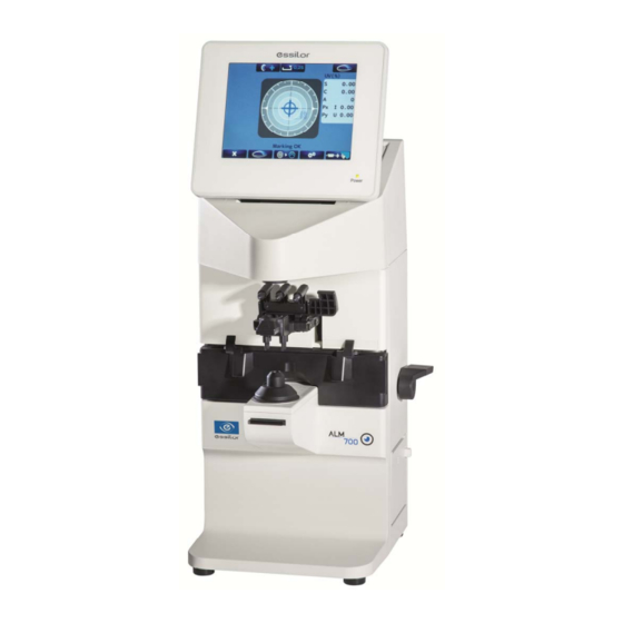
2. Device 2.1 General Descritpion of Device This device aims to take the measurements of SPH, CYL, AXIS, prism refractive power and optical axis coordinate of unprocessed lens, processed framed lens and contact lens, and to put dots on them to find its axis. As an external feature, the angle of the LCD can be changed. - Page 10 Color LCD with 640 X 480 dots User-friendly LCD which is adjustable vertically within operating range (60°) Touch panel is adopted. Pilot lamp Lamp to indicate ON (light on)/ OFF (light off) and power saving mode (blink) Marking lever/ lens holder The marking lever and lens holder are integrated.
-
Page 11: Instructions For Use
3. Instructions for Use 3.1 Installation (1) Do not expose the device to sunlight or bright light from lighting equipments. Take extra caution to avoid strong light because it may cause the failure of measurement. NOTE Do not install the device in places where either dust or rubbish may accumulate. -
Page 12: Connection/ Wiring
3.2 Connection/ Wiring (1) The earth cable of the power code should be connected to the earth terminal. (2) Avoid damaging the power cord (such as bending it in an extremely small size, pulling, placing a heavy object on it etc.). Also, do not fabricate the cord. (3) When the power cord is damaged, (breaks, damage of cover etc.), replace it to the new one. -
Page 13: Disposal
(3) If the main unit cover or operation panel is dirty, gently wipe it with a dry cloth. For hard to remove stains, a damp cloth or neutral cleanser is recommended. Avoid using organic solvent such as thinner which may damage the water based paint finish or device. -
Page 14: Measurement Screen
4. Measurement Screen 4.1 Description of Measurement Screen Type of lens: left/ Measurement setting right/ single AXIS mark Display of alignment condition or error Cross cursor message Measurement screen of single focus lens, multifocal lens and contact lens ※ The display of the measurement screen reflects the setting and condition of the device. The touch panel is adopted. -
Page 15: Preparation For Measurement
4.2 Preparation for Measurement 4.2.1 Device Setting This device is ready for use with the standard mode but the setting can be changed easily as needed. Switch to the Setup (setup of device) screen by touching at the bottom of screen. Change of switch function The functions of each switch are changed on the menu screen. - Page 16 【2/4 screen】 Item Description of Function Selects if performing UV transmission measurement or not Measure On:Perform / Off: Not perform Selects if displaying UV transmission graph or not (displayed only on the progressive lens Graph measurement screen) On:Perform / Off: Not perform Selects if displaying the assessment graph Prog.
-
Page 17: Id Screen
【4/4 screen】 Item Description of Function Date/Time Switches to Date/Time screen Displays the Setup items Default changed from default and changes the setting back to the Setting default by pressing 4.2.3 ID Screen This screen is to create the data for printing out the distributor’s name or message on the printout. -
Page 18: Data Output Screen
4.2.4 Data Output Screen This screen is to set the communication parameter for outputting the measurement values to the externally-connected PC etc. The measurement values and data created on the “ID Screen” are output by selecting “RS232C” or “Both” of “Data Output” on the Setup screen. The output content is same with the one of the printout. -
Page 19: Data/Time Screen
4.2.5 Data/Time Screen The screen to set the date and time for printout and communication output Select the item to be changed with and set the detail with “Date Form”:YMD → Year, Month, Day “Date Form”:DMY → Day, Month, Year “Date Form”:MDY →... -
Page 20: Operating Instructions Of Device
5. Operating Instructions of Device 5.1 Lens Holder Operational (1) Raise the lever to the operational direction direction until it is unlocked. (2) Lower the lens holder slowly and fix the lens. Do not give strong impact to a lens when lowering the lens holder. When rising the lens holder, make sure to move to the top. -
Page 21: Marking Lever
5.3 Marking Lever Marking lever 5.3.1 Operating Instructions (1) Turn and lower the marking lever. (2) Place the tips of the marking pens on the lens surface softly. Do not mark several times at the same point. The marking pen may be worn out quickly. (3) Release the finger after marking. -
Page 22: Replacement Of Marking Pen
5.3.2 Replacement of Marking Pen The marking pen is the consumable item. Replace it if the imprint becomes thin or the pen tip is worn. (1) Remove the marking pen by pressing and rotating it 90 degrees as shown below. (2) Insert the new pen back to the initial position as shown below. -
Page 23: Printer
5.4 Printer 5.4.1 Operating Instructions The measurement values can be printed out by touching after taking a measurements. Distributor’s name, comment etc. (printed out only when ID is set) Number of characters input: Add measurement values are 44 characters (22 characters X 2 lines) displayed only at the time of measurements of multifocal lens and progressive lens... -
Page 24: Installation And Replacement Of Printer Paper
・Prism Over ・Center Error ESSILOR ALM700 ESSILOR ALM700 5.4.2 Installation and Replacement of Printer Paper (1) Open the printer cover by pressing the printer cover button. Printer cover button (2) Insert the printer paper with attention to the winding direction. -
Page 25: Replacement Of Fuse
(3) Close the printer cover with the end of the paper taken out a little. At this time, close it completely until hearing the clicking noise. The error is displayed and the data is not printed out if the cover is opened. Printer paper Use the printer paper specified for “ALM700”. -
Page 26: Measurement
6. Measurement 6.1 Checkup before Measurement Lens under lens stand The lens holder is set properly. The lens under the lens stand is clean. (In case that the lens is dirty, clean it with a soft cloth.) Lens stand is removed ... -
Page 27: Measurement Of Single Lens
6.2 Measurement of Single Lens (1) Place the lens on the lens stand. Lower the lens holder softly on the lens. The screen as shown on the right appears. Do not give strong impact to a lens when lowering the lens holder. When rising the lens holder, make sure that it is moved to the top and locked. -
Page 28: Measurement Of Framed Lens
6.3 Measurement of Framed Lens Lens holder (1) Place the framed lens on the lens stand and lower the Lens plate lens holder softly on the lens. Move the lens plate to the near side with the lens plate lever so that the bottom of the lens touches the lens plate. -
Page 29: Pupillary Distance (Pd) Measurement
6.4 Pupillary Distance (PD) Measurement 6.4.1 Device Setting On the setup screen, confirm that “PD Measure” is set as “On”, and the lens measurement is set for both of right and left lens. ※ In case that “PD Measure” is “Off”, the PD measurement value and measurement area are not displayed. -
Page 30: Measurement Of Multifocal Lens
6.5 Measurement of Multifocal Lens (1) Place the lens on the lens stand and hold it with the lens holder softly. (2) Take a measurement of far point, and press the Memory/ Add switch. SPH, CYL, AX and prism values are stored. -
Page 31: Measurement Of Progressive Lens
6.6 Measurement of Progressive Lens (1) Take a measurement of progressive lens. Set “Auto Prog.” and “ADD Measure”. Auto Prog. Off :No auto judgment for a progressive lens On :Auto judgment for a progressive lens ADD Measure F/N.AT :Auto memory of far and near points N.AT :Auto memory of near point Manual :Manual memory of far and near points (2) Switching to progressive lens measurement screen... - Page 32 (3) Measuring procedure of progressive lens (when N.AT is selected for ADD Measure) 1) Detection of progressive zone First, find the progressive zone by moving the lens back and forth, and right and left slowly. The cross cursor (screen shown below) appears when the progressive zone is found. Press the Memory/Add switch in case that the progressive zone cannot be detected because ADD value is small etc.
- Page 33 (4) Display of ADD value and assessment graph, and manual operation (when “Manual” of “ADD Measure” is selected) When setting “Prog. Graph” as “On” on the Setup screen, the graph is displayed on the progress lens measurement screen. Depending on the type of lens, it may be difficult to detect each point automatically even though normally the near and far points are detected automatically.
-
Page 34: Measurement Of Ultraviolet (Uv) Transmission
6.7 Measurement of Ultraviolet (UV) Transmission Checks the UV protection function by taking a measurement of the UV transmission of lens. The light wavelength for UV transmittance measurement is 375 nm. This does not measure the transmittance of a whole area of UV light. 6.7.1 Device Setting Confirm that “UV Measure”... -
Page 35: Measurement Of Contact Lens
6.8 Measurement of Contact Lens 6.8.1 Preparation (1) In case of taking a measurement of hard contact lens, select “H CL” on Setup screen. In case of taking a measurement of soft contact lens, select “S CL” on Setup screen. (2) Change the lens stand to the accompanying contact lens stand. -
Page 36: Marking
7. Marking Refer to “5.3. Marking Lever.” 7.1 Lens without Astigmatism (1) Overlap the cross cursor with the alignment mark on the screen by moving the lens. You are ready for marking when the message “Marking OK” is displayed. (2) Lower the marking lever to mark on the lens. 7.2 Lens with Astigmatism ... -
Page 37: Marking Of Prism Lens
7.3 Marking of Prism Lens In case that prescription is expressed in X-Y (1) Select “X-Y” from “Prism” on the “Setup” screen. (2) Move the lens so that the prism values displayed on the screen match with the ones on the prescription. The meanings of the prism values displayed are as shown below. -
Page 38: Other Functions
8. Other Functions 8.1 Auto Memory Function This device has the function to store the measurement values in memory automatically when the alignment is achieved, and the message “Marking OK” is displayed at the time of the measurements of single focal lens, multifocal lens and contact lens. 8.1.1 Operation Procedure Move the cursor to “Auto Memory”... -
Page 39: Power Saving Function
8.2 Power Saving Function The power saving function is activated if no switches are operated or no measurement values are updated with the power on. The switching time to the power saving mode can be set on “Standby” of the Setup screen. While this function is activated, the power to the measurement light and LCD monitor is Measurement mode... -
Page 40: Error Display
9. Error Display An error message appears when the measurement condition or measurement result is judged as unreasonable. Also, an error message appears when the performance of the device is abnormal. 9.1 Type ※ Display with a three-digit code (number) Message Status Error Detail... -
Page 41: Error Handling Procedure
9.2 Error Handling Procedure Do not disassemble, remodel or repair. Warning It may cause electric shock. ・Initial Error This message appears if the lens is placed on the lens stand when the power is turned on or the lens under the lens stand is dirty. Remove the lens. -
Page 42: Storage Of Device
10. Storage of Device (1) Points to be checked for long-term storage Turn OFF the power. Remove the power cord from the outlet. Put the dust proof cover on the main unit. (2) Notes on storage environment (3) Avoid storage under the following conditions ... -
Page 43: Specification
11. Specification Sphere -25D to +25D (0.01/0.12/0.25 step) Cylinder 0 to ±10D (0.01/0.12/0.25 step) Axis 0 to 180° (1°) Measurement range Addition 0 to +10D (0.01/0.12/0.25 step) 0 to 10△ Prism (0.01/0.12/0.25 step) Unprocessed lens Single lens, multifocal lens, progressive (diameter:100mm) lens Measurable lens... -
Page 44: Emc (Electromagnetic Compatibility)
12. EMC (Electromagnetic Compatibility) This device conforms to the requirements of the EMC (electromagnetic compatibility) standard as shown below. Guidance and manufacturer’s declaration – electromagnetic emissions This device is intended for use in the electromagnetic environment specified below. The customer or user of this device should assure that it is used in such an environment. Emission test Compliance Electromagnetic environment –... - Page 45 Guidance and manufacture’s declaration – electromagnetic immunity This device is intended for use in the electromagnetic environment specified below. The customer or user of this device should assure that it is used in such an environment. IEC 60601 Electromagnetic environment Immunity test Compliance level test level...
- Page 46 Guidance and manufacturer’s declaration – electromagnetic immunity This device is intended for use in the electromagnetic environment specified below. The customer or the user of this device should assure that it is used in such an environment. IEC60601 Compliance Immunity test Electromagnetic environment - guidance test level level...
- Page 47 disturbances are controlled. The customer or the user of this device can help prevent electromagnetic interference by maintaining a minimum distance between portable and mobile RF communications equipment (transmitters) and this device are recommended below, according to the maximum output power of the communications equipment. Separation distance according to frequency of transmitter Rated maximum output power of...
- Page 50 Essilor Instruments USA 8600 W. Catalpa Avenue, Suite 703 Chicago, IL 60656 Phone: 855.393.4647 Email: info@essilorinstrumentsusa.com www.essilorinstrumentsusa.com...
Need help?
Do you have a question about the ALM 700 and is the answer not in the manual?
Questions and answers