
Related Manuals for SCHUNK RST-P 060


Summary of Contents for SCHUNK RST-P 060
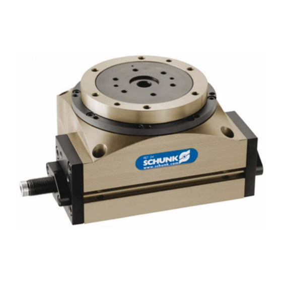
- Page 1 Assembly and Operating Manual Ring indexing table RST-P 060 / 087 Translation of original operating manual Superior Clamping and Gripping...
- Page 2 Imprint Copyright: This manual remains the copyrighted property of SCHUNK GmbH & Co. KG. It is solely supplied to our customers and operators of our products and forms part of the product. This documentation may not be duplicated or made accessible to third parties, in particu- lar competitive companies, without our prior permission.
-
Page 3: Table Of Contents
8.1 Start-up ........................20 8.1.1 Measures for start-up ................. 20 8.1.2 Starting up the module ................20 8.2 Actuation / operation ..................... 21 8.2.1 Actuation of clockwise pulsing ..............21 8.2.2 Actuation of anti-clockwise pulsing ............23 02.01|RST-P 060 / 087|en... - Page 4 11 Assembly drawings ....................34 11.1 RST-P060 assembly ....................34 11.2 RST-P087 assembly ....................35 12 Wearing parts ......................36 12.1 RST-P060 wearing parts..................36 12.2 RST-P087 wearing parts..................37 13 Translation of original declaration of incorporation ..........39 02.01|RST-P 060 / 087|en...
-
Page 5: About This Manual
Non-compliance may cause irreversible injury or death. CAUTION Dangers for persons. Non-observance may cause minor injuries. NOTICE Information about avoiding material damage 1.1.2 Symbols Warning about a danger point Warning about hand injuries General mandatory sign to prevent material damage 02.01|RST-P 060 / 087|en... -
Page 6: Applicable Documents
About this manual Applicable documents • General terms of business • Catalog data sheet of the purchased product • Assembly and Operating Manuals of the accessories The documents listed here, can be downloaded on our homepage www.schunk.com 02.01|RST-P 060 / 087|en... -
Page 7: Basic Safety Notes
• Do not subject the module to excessive vibrations and/or me- chanical shocks. • Strong magnetic fields can impair the function of the module. If the product is to be used in strong magnetic fields, contact your SCHUNK partner. 02.01|RST-P 060 / 087|en... -
Page 8: Product Safety
Provide protective equipment per EC Machinery Directive. 2.4.2 Constructional changes, attachments, or modifications Additional drill holes, threads, or attachments that are not offered as accessories by SCHUNK may be attached only with permission of SCHUNK. Personnel qualification The assembly, initial commissioning, maintenance, and repair of the module may be performed only by trained specialist person- nel. -
Page 9: Using Personal Protective Equipment
Risk of injury from objects falling and being ejected • The danger zone must be surrounded by a safety fence during operation. WARNING Risk of injury due to rotating components! Avoidance: The danger zone must be surrounded by a safety fence during operation. 02.01|RST-P 060 / 087|en... -
Page 10: Warranty
• Exact type designation of the compatible sensors see ☞ cata- log. • If you require further information on sensor operation, contact your SCHUNK contact person or download information from our homepage. • For mounting the sensors, mounting kits are partly necessary. -
Page 11: Technical Data
Overturning moment Tangential moment Permissible pulsing / swiveling times ☞ catalog data Operating data for compressed air connection Pressure medium Compressed air, standard for quality of the compressed air according to ISO 8573-1: 7 4 4 02.01|RST-P 060 / 087|en... - Page 12 Damage to the ring indexing table due to incorrect use of un- oiled compressed air. Due to washing out of the factory lubrication • The unit may not under any circumstances have been operat- ed with oiled air before operation with unoiled air. 02.01|RST-P 060 / 087|en...
-
Page 13: Assembly And Settings
• Onto the base with screws from above • To the rear mounting surface Fig. 1 Mounting to the base - screwing on from below Fig. 2 Mounting to the base - screwing on from above 02.01|RST-P 060 / 087|en... - Page 14 Screw, ISO 4762 M5 / 4x M5 / 4x Centering sleeve ZH 700 (2x) ZHU 10 (2x) * must be supplied by the customer, depending on type of at- tachment. ** included in the module's scope of delivery 02.01|RST-P 060 / 087|en...
-
Page 15: Air Connection
Remove the energy supplies before starting with assembly and adjustments. Make sure that no residual energy remains in the system. NOTICE Observe the requirements for the air supply. ( 6, Page 11) "Technical Data" Fig. 4 Air connections 02.01|RST-P 060 / 087|en... -
Page 16: Sensors
The module is ready to use numerous sensors. • If you require further information on sensor operation, contact your SCHUNK contact person or download information from our homepage. • Technical data for the sensors can be found in the data sheets (included in the scope of delivery). -
Page 17: Mms Sensor Attachment
( 7.2, Page 15). 3 Adjust the sensor (2) to piston position and lock into place us- ing an Allen key. 4 If need be, repeat the procedure with the second sensor and the opposing piston position. 02.01|RST-P 060 / 087|en... -
Page 18: Setting The Swiveling Time
• Always set back the back stop (17) and dampers (45) to the extent that the module performs the full angle stroke (90°, 60°, 45° or 30°) and can be pulsed on. 02.01|RST-P 060 / 087|en... - Page 19 3 Tighten screws (51). 4 Check the dampening in operation and correct the setting if necessary. The elastomer damper is set correctly if the piston reaches its end position during reverse stroke without mechanical impact. 02.01|RST-P 060 / 087|en...
-
Page 20: Handling And Operation
( 7.2, Page 15). 2 Setting the swiveling time ( 7.4, Page 18). 3 Setting the end position dampers ( 7.5, Page 18). 4 Test run as per actuation ( 8.2, Page 21). 5 Correct settings, if necessary. 02.01|RST-P 060 / 087|en... -
Page 21: Actuation / Operation
Handling and operation Actuation / operation 8.2.1 Actuation of clockwise pulsing Fig. 8 CW: Clockwise ACW: Anti-clockwise 02.01|RST-P 060 / 087|en... - Page 22 CW (falling edge), operations can be performed on the ro- tary table before new pulsing starts. 6 Sensor reaches end position ACW: Drive piston is in end posi- tion ACW, home position is reached. 7 Introduction of new pulsing 02.01|RST-P 060 / 087|en...
-
Page 23: Actuation Of Anti-Clockwise Pulsing
Handling and operation 8.2.2 Actuation of anti-clockwise pulsing Fig. 9 CW: Clockwise ACW: Anti-clockwise 02.01|RST-P 060 / 087|en... - Page 24 CW (falling edge), operations can be performed on the ro- tary table before new pulsing starts. 6 Sensor reaches end position CW: Drive piston is in end posi- tion CW, home position is reached. 7 Introduction of new pulsing 02.01|RST-P 060 / 087|en...
-
Page 25: Conversion/Change Of Operating Modes Left-Pulsing L (Acw) ←→ Right-Pulsing (Cw) ←→ Operation On Both Sides B
The stroke reductions must always be mounted on the same side as the damper. 6 Screw in dampers and back stop opposite to the original side. 7 Setting the damper and the back stop ( 7.5, Page 18). 8 Tighten the 4 screws (51). 02.01|RST-P 060 / 087|en... -
Page 26: Conversion Of Left- Or Right-Pulsing Operation To Operation On Both Sides
5 Tighten the two screws (51). Conversion of pitch The customer can modify the pitches 4 / 6 / 12. Conversion to or from pitch 8 can only be done by SCHUNK. In this case, please consult your SCHUNK contact person. WARNING... - Page 27 6.54 9.81 X [mm] 9.41 14.12 Tool The tool is required for converting the pulsing on unit RST-P087. Fig. 11 Tool Dimension A [mm] Ø12 B [mm] C [mm] Do not counterbore M8 thread D [mm] 02.01|RST-P 060 / 087|en...
- Page 28 8.2.1, Page 21) kit. Use tool, as required (☞ previous diagram). 3 Assemble cover plate (13/14). 4 Adjust the shock absorber (45) ( 7.5, Page 18). 5 Tighten the 4 screws (51). 02.01|RST-P 060 / 087|en...
-
Page 29: Troubleshooting
Check compressed air lines. Component is broken, e.g. through over- Replace component or send the module loading with a repair order to SCHUNK. Ensure that the module was only used within its defined application parameters. Module does not lock correctly (... -
Page 30: Signal For Piston Position Or Zero Point Cycle Ring Monitoring Missing
Check swiveling time and adjust with ex- haust air throttles as necessary ( 7.2, Page 15) Shock absorber not well adjusted Readjust damper setting ( 7.5, Page 18) Unfavorable installation Check design RST-P type too small User larger RST-P type 02.01|RST-P 060 / 087|en... -
Page 31: Cycle Times Are Not Reached
Compressed air lines between module and control valve shoud be kept as short as poss- ible. Flow rate of valve is sufficiently large rela- tive to the compressed air consumption. Dampening not ideally set Readjust damper setting ( 7.5, Page 18) 02.01|RST-P 060 / 087|en... -
Page 32: Maintenance And Care
10.3 Lubricants (basic lubrication) We recommend the lubricants listed. During maintenance, treat all greased areas with lubricant. Thinly apply lubricant with a lint-free cloth. Lubrication point Lubricant All seals Isoflex-Topas NCA 52 Bores on the piston 02.01|RST-P 060 / 087|en... -
Page 33: Piston And Seals
The module must only be disassembled by the customer to the extent shown in the following chapter. • Further disassembly may only be done by SCHUNK as other- wise the mechanism or internal electronics may be damaged. 02.01|RST-P 060 / 087|en... -
Page 34: Assembly Drawings
Assembly drawings Assembly drawings 11.1 RST-P060 assembly Fig. 12 RST-P060 assembly * Wearing parts 02.01|RST-P 060 / 087|en... -
Page 35: Rst-P087 Assembly
Assembly drawings 11.2 RST-P087 assembly Fig. 13 RST-P087 assembly * Wearing parts 02.01|RST-P 060 / 087|en... -
Page 36: Wearing Parts
The wearing parts listed below cannot be replaced by the custom- Defects in the drive and in the locking mechanism must be recti- fied by SCHUNK. In this case, please consult your SCHUNK contact person. other wearing parts Item Quantity... -
Page 37: Rst-P087 Wearing Parts
The wearing parts listed below cannot be replaced by the custom- Defects in the drive and in the locking mechanism must be recti- fied by SCHUNK. In this case, please consult your SCHUNK contact person. other wearing parts Item Quantity... - Page 38 Notes Notes 02.01|RST-P 060 / 087|en...
-
Page 39: Translation Of Original Declaration Of Incorporation
Bahnhofstr. 106 – 134 D-74348 Lauffen/Neckar We hereby declare that the following product: Product designation: Ring indexing table / RST-P 060 / 087 / electro-pneumatic ID number 0314510 … 0314533 meets the applicable basic requirements of the Machinery Directive (2006/42/EC). - Page 40 02.01|RST-P 060 / 087|en...
Need help?
Do you have a question about the RST-P 060 and is the answer not in the manual?
Questions and answers