Epson Perfection 4870 Photo Service Manual
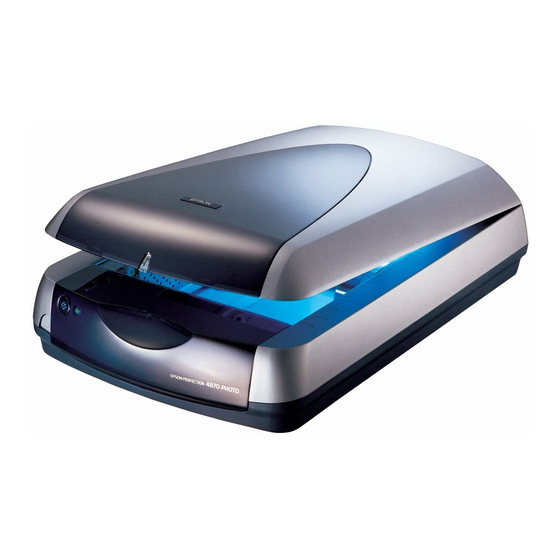
Color image scanner
Hide thumbs
Also See for Perfection 4870 Photo:
- Brochure & specs (5 pages) ,
- Start here manual (9 pages)
Table of Contents
Advertisement
Advertisement
Table of Contents

Related Manuals for Epson Perfection 4870 Photo


Summary of Contents for Epson Perfection 4870 Photo
- Page 1 Service Manual Color Image Scanner EPSON Perfection 4870 Photo SESC03-008...
- Page 2 SEIKO EPSON CORPORATION. All effort have been made to ensure the accuracy of the contents of this manual. However, should any errors be detected, SEIKO EPSON would greatly appreciate being informed of them.
- Page 3 1. REPAIRS ON EPSON PRODUCT SHOULD BE PERFORMED ONLY BY AN EPSON CERTIFIED REPAIR TECHNICIAN. MAKE CERTAIN THAT THE SOURCE VOLTAGES IS THE SAME AS THE RATED VOLTAGE, LISTED ON THE SERIAL NUMBER/RATING PLATE. IF THE EPSON PRODUCT HAS A PRIMARY AC RATING DIFFERENT FROM AVAILABLE POWER SOURCE, DO NOT CONNECT IT TO THE POWER SOURCE.
- Page 4 Provides Epson-approved methods for adjustment. result in damage to, or destruction of, equipment. CHAPTER 6.MAINTENANCE Provides preventive maintenance procedures and the lists of Epson-approved lubricants and adhesives required for servicing C H E C K May indicate an operating or maintenance procedure, the product.
- Page 5 Revision Status Revision Date of Issue Description December 10, 2003 First release...
-
Page 6: Table Of Contents
Perfection 4870 Photo Revision A Contents Chapter 1 PRODUCT DESCRIPTION Chapter 3 TROUBLESHOOTING 1.1 Features........................9 3.1 Overview ......................30 3.1.1 Self-diagnostic Function................30 1.2 Basic specification....................10 3.2 Troubleshooting....................31 1.3 Interface Specifications ..................13 1.3.1 IEEE1394....................13 1.3.2 USB......................13 Chapter 4 DISASSEMBLY/ASSEMBLY 1.4 Exterior Specifications .................. - Page 7 Perfection 4870 Photo Revision A Chapter 5 ADJUSTMENT Chapter 6 MAINTENANCE 6.1 Overview ......................66 6.1.1 Cleaning ...................... 66 6.1.2 Lubrication....................67 Chapter 7 APPENDIX 7.1 Connector Configuration ..................69 7.1.1 Connector Configuration ................69 7.1.2 Connector Connection Table ..............69 7.2 Circuit Diagrams ....................
-
Page 8: Chapter 1 Product Description
C H A P T E R PRODUCT DESCRIPTION... -
Page 9: Features
1.1 Features Easy operation EPSON Smart Panel 3.0 The main features of the Perfection 4870 Photo are as follows. Scan to PDA and PDF support Achieved easy scanning with a start button Fast, high-quality A4 color image scanner optimum for consumer/SOHO Ease of exporting image data to an application applications. -
Page 10: Basic Specification
White Cold cathode Fluorescent Lamp IR LED (For Digital ICE for Film) Dimensions 304 (W) x 476 (D) x 134 (H) mm Start Button 1 push Button: Ease of use with EPSON Smart Panel Refer to Figure 1-3 Driver EPSON Scan Weight 6.7kg... - Page 11 *5: For standard equipped by Pre-install PC or upgraded PC from Windows Within 45sec (5ºC) 2000 Professional model only *6: EPSON Scan (EPSON driver)/SilverFast® works independently or only with Adobe® Photoshop® 7.0 on Mac OS X native mode. Some applications and/or functions only work in Mac OS X classic mode.
- Page 12 Perfection 4870 Photo Revision A ELECTRICAL SPECIFICATIONS ELECTRICAL NOISE RESISTANCE Rated Input voltage AC100 - 120V (100V) Static electricity Contact discharge 4.5kV AC220 - 240V (200V) Air discharge 8.5kV Rated Input Frequency 50 - 60Hz (100V, 200V) ENVIRONMENTAL CONDITIONS Power consumption...
-
Page 13: Interface Specifications
Perfection 4870 Photo Revision A 1.3 Interface Specifications 1.3.1 IEEE1394 In compliance with IEEE Std 1394a-2000 The interfaces of this scanner are shown below. In compliance with ANSI X3T10 Serial Bus Protocol 2 Revision4L (SBP-2) IEEE1394 USB2.0 OPTION 6 pin connector x 1 1.3.2 USB... -
Page 14: Exterior Specifications
Turns the scanner on and off When the power is turned on, the scanner is initialized. Start Button Starts the EPSON Smart Panel. The status of this button can be checked by [ESC !] 1.4.2 Explanation of indications Explanation of indications... -
Page 15: Outside Drawing
Dimensions and Weight Dimensions 304 (W) x 476 (D) x 134 (H) mm Weight 6.7kg Package size Dimensions 405 (W) x 573 (D) x 230 (H) mm Unit: mm Figure 1-3. Outside Drawing of Perfection 4870 Photo PRODUCT DESCRIPTION Exterior Specifications... -
Page 16: Control Codes
Perfection 4870 Photo Revision A 1.5 Control Codes Table 1-2. Control Code List Category Command Name Code Following table is the list of control codes of the scanner. Scan mode setting ESC g i Initialization ESC @ Table 1-2. Control Code List... -
Page 17: Error-Time Processing
Perfection 4870 Photo Revision A 1.6 Error-time Processing Table 1-3. Error Definition and Remedy List Receivable Category LED Indication Cause Remedy Recovery Command An undefined command or • The scanner ignores the incorrect The error condition is cleared when undefined command parameter was command or parameter. -
Page 18: Scanning Range
Perfection 4870 Photo Revision A 1.7 Scanning Range 1.7.2 Transparent document Size 144 x 231mm (horizontal x vertical) 1.7.1 Reflective document Size 216 x 297mm (horizontal x vertical) 37.9 ± 1.5mm 144mm 216mm 1.0 ± 0.5mm 21.6 ± 1.5mm 1.0 ± 0.5mm... - Page 19 C H A P T E R OPERATING PRINCIPLES...
-
Page 20: Engine Operation Outline
Perfection 4870 Photo Revision A 2.1 Engine Operation Outline CCD Board Forms an alternative six-lines color CCD (R, G, B independent) and its control and drive circuits. This section explains the functions and operating principles of the Perfection 4870 Inverter Board Boosts +24VDC and converts DC to AC to generate Photo Engine. -
Page 21: Tpu Carriage Unit Outline
Perfection 4870 Photo Revision A 2.1.1.2 TPU Carriage Unit outline TPU Inverter Board Boosts +24VDC and converts DC to AC to generate the voltage for driving the Lamps (white cool cathode The TPU Carriage Unit consists of TPU Inverter Board, Lamps (light source), SUB_C fluorescent lamps). -
Page 22: Moving Mechanism Operation
Perfection 4870 Photo Revision A 2.1.2 Moving Mechanism operation The Carriage Unit slides along the guide rail in the sub scanning direction. To perform this sliding operation, the CR (Carriage) Motor transmits its drive power to the CR 2.1.2.1 Carriage Moving Mechanism operation Timing Belt, which is fixed to the Carriage Unit, via the Drive Pulley and Deceleration Gear. -
Page 23: Tpu Carriage Moving Mechanism Operation
Perfection 4870 Photo Revision A 2.1.2.2 TPU Carriage Moving Mechanism operation The TPU Carriage Unit slides along the guide rail in the sub scanning direction. To perform this sliding operation, the TPU CR (Carriage) Motor transmits its drive power to the TPU CR Timing Belt, which is fixed to the Carriage Unit, via the Drive Pulley and the Deceleration Gear. -
Page 24: Digital Ice Function Operation
Perfection 4870 Photo Revision A 2.2 Digital Ice function operation 2.2.2 Film-Ice function Film-Ice function outline This scanner has the Digital Ice function, which is divided into two types according to Longer in wavelength than a visible light, an infrared light has a property that it the document type. - Page 25 Perfection 4870 Photo Revision A Film-Ice function sequence Read the visible light position (To recognize the home position of image scanning, it reads two holes of the Upper Housing Scale section). Scan a visible-light image. Scan an infrared-light image. Superimposes the images obtained from each light and detects the flaws and/or the foreign matter.
-
Page 26: Power Supply Circuit
Perfection 4870 Photo Revision A 2.3 Power Supply Circuit This Power Supply Circuit Board generates DC power necessary to drive the Control Board and Scanner Engine. Table 2-1 indicates the Power Supply Circuit Boards on a destination basis. Table 2-1. Destination-based Power Supply Circuit Boards Specifications Unit Part No. -
Page 27: Control Circuit
Perfection 4870 Photo Revision A 2.4 Control Circuit SUB_C Board Table 2-6. IC Explanation 2.4.1 Power Supply Circuit operation outline Location Location PSSI2021SAY PSS2021SAY The Control Circuit of this scanner consists of the following circuits. SUB_D Board Main Board Table 2-7. IC Explanation Table 2-3. -
Page 28: Image Processing Operation
Perfection 4870 Photo Revision A 2.4.2 Image processing operation The sequence of scanned image processing is explained in order below. CCD Board (CCD Image Sensor) Optoelectronic transformation processing (reflected light (optical energy) from a document surface is transformed into electric charge (electric energy)) - Page 29 C H A P T E R TROUBLESHOOTING...
-
Page 30: Overview
Perfection 4870 Photo Revision A 3.1 Overview This chapter explains the remedies for errors detected by the self-diagnostic function as well as the check points on a fault phenomenon basis, which are required for efficient troubleshooting at occurrence of any error. -
Page 31: Troubleshooting
Perfection 4870 Photo Revision A 3.2 Troubleshooting Table 3-3. Trouble Phenomena, Causes and Reference Flowcharts Reference Phenomenon Trouble Definition Cause Location Flowchart This section explains troubleshooting from the superficial phenomena. Occurrence of The host does not • Condition of host In this section, troubleshooting is divided on a unit level, based on the superficial "Communication... - Page 32 Perfection 4870 Photo Revision A Start Start Has the Release the Carriage Lock been Reexamine the Are all connectors Carriage Lock. released? normal? connection. Is the Housing Has the fuse Install it normally. Upper installed Replace the Power of the power correctly? Supply Board.
- Page 33 Perfection 4870 Photo Revision A Start Start Is the Document Remove smudge. (Refer to Glass free from "Chapter 6 6.1.1Cleaning".) smudge, etc.? Is the Harness Connect the connected to the Harness. *Image has white spots. Main Board and Carriage? Are the Mirrors in the Remove smudge.
- Page 34 Perfection 4870 Photo Revision A Start Start Is the Does the host TPU Cable on Replace the host. support USB and the rear of the Connect the Cable. IEEE1394? scanner connected securely? * Has "USB" been made valid after choosing "My Computer"...
- Page 35 Perfection 4870 Photo Revision A Start Start Is the TPU Harness Connect the TPU connected to the TPU Main Board and TPU Harness. Has the Release the TPU Carriage? TPU Carriage Lock Carriage Lock. been released? Is the Connector CN2...
- Page 36 Perfection 4870 Photo Revision A Start Is the TPU Harness connected Connect the TPU to the TPU Main Harness. Board and TPU Carriage? Is the Connector CN2 Connect the connected to the Connector. TPU Main Board? Are the Connectors Connect the...
- Page 37 C H A P T E R DISASSEMBLY/ASSEMBLY...
-
Page 38: Overview
Perfection 4870 Photo Revision A 4.1 Overview The following figure shows the definition of the scanner orientations explained in the disassembly procedure. This chapter explains the procedures for disassembling the major units and parts of the Inside product. Unless otherwise explained, reassembly should be carried out in the reverse order of the disassembly procedure. -
Page 39: The List Of Recommended Screws
Perfection 4870 Photo Revision A 4.1.3 The List of Recommended Screws The following table indicates the screws used in the Perfection 4870 Photo. Table 4-2. The List of Recommended Screws Standard Outline C.B.P M3x6 (+) Bind P-tite Screw C.B.P M3x8 (+) Bind P-tite Screw C.B.P M3x12... -
Page 40: Disassembly Procedure
Perfection 4870 Photo Revision A 4.2 Disassembly Procedure This section illustrates how to remove the main components of this product. Unless otherwise specified, the reassembly procedure is omitted here since the product can be reassembled in the reverse order of the disassembly procedure. For the engagement of the main components, refer to the general exploded views in the Appendix. -
Page 41: Removal Of Document Cover
Perfection 4870 Photo Revision A 4.2.1 Removal of Document Cover Open the Document Cover. Disconnect the TPU Unit Connector on the rear side of the Main Unit. Document Cover TPU Unit Connector Figure 4-3. Disconnection of TPU Unit Connector Figure 4-4. Removal of Document Cover (1) Hold both ends of the Document Cover and then lift and remove it. -
Page 42: Removal Of Upper Housing
Perfection 4870 Photo Revision A 4.2.2 Removal of Upper Housing Lift the rear side of the Upper Housing, slide it to the front, release the three hooks, and remove the Upper Housing. Remove the Document Cover. (Refer to 4.2.1 Removal of Document Cover ) Upper Housing Release the Carriage Lock on the left side of the Main Unit with a coin or like. -
Page 43: Removal Of Panel Board
Perfection 4870 Photo Revision A 4.2.3 Removal of Panel Board Remove of Upper Housing. (Refer to 4.2.2 Removal of Upper Housing ) Remove the two screws (C.B.P M3x8) which secure the Panel Board and then remove SW Connector Cable Notches C.B.P M3x8... -
Page 44: Removal Of Main Board
Perfection 4870 Photo Revision A 4.2.4 Removal of Main Board Remove the two screws (C.B.S M3x5) which secure the Main Board Cover. Remove the Main Board Cover in the following procedure. Remove of Upper Housing. (Refer to 4.2.2 Removal of Upper Housing ) Release the hook A and the hook B, and lift the rear side of the Main Board Move the Carriage Unit to the centre. - Page 45 Perfection 4870 Photo Revision A Disconnect the CR Motor Connector, Carriage FFC, and Power Supply Board Pass the Carriage FFC through the Ferrite Core and adhere it Connector connected to the Main Board. with a two-sided tape at the position shown in Figure 4-15.
-
Page 46: Removal Of Carriage Unit
Perfection 4870 Photo Revision A 4.2.5 Removal of Carriage Unit While lifting the Carriage Unit as shown in Figure 4-19, remove the rear part of the Carriage Shaft from the notch, and pull the front part out of the Bushing. - Page 47 Perfection 4870 Photo Revision A Disconnect the Carriage FFC from the Main Board. (Refer to Step 3 to Step 5 in 4.2.4 Removal of Main Board.) Remove the Carriage FFC from the Base Frame and then remove the Carriage Unit.
-
Page 48: Removal Of Cr Motor Unit
Perfection 4870 Photo Revision A 4.2.6 Removal of CR Motor Unit Remove the CR Timing Belt from the Driven Pulley. Remove of Carriage Unit. (Refer to 4.2.5 Removal of Carriage Unit ) CR Timing Belt Driven Pulley Remove the three screws (C.B.S M3x5) which secure the CR Motor Unit and then remove the CR Motor Unit. -
Page 49: Removal Of Driven Pulley
Perfection 4870 Photo Revision A 4.2.7 Removal of Driven Pulley Get the ends of the Torsion Spring caught in the two hooks as shown in Remove the CR Timing Belt from the Driven Pulley. (Refer to Step 1 to Step 3 in 4.2.6 Figure 4-26. -
Page 50: Removal Of Sub_A Board
Perfection 4870 Photo Revision A 4.2.8 Removal of SUB_A Board While lifting the front part of the Base Frame, remove the screw (C.B.S M3x5) and two hooks which secure the SUB_A Board and then remove the SUB_A Board. Remove of Upper Housing. -
Page 51: Removal Of Power Supply Board
Perfection 4870 Photo Revision A 4.2.9 Removal of Power Supply Board Disconnect the Main Board Connector from the Power Supply Board. Remove the five screws (C.B.S M3x5) which secure the Power Supply Board and then Remove of Carriage Unit. (Refer to 4.2.5 Removal of Carriage Unit ) remove the Power Supply Board from the Power Supply Board Cover. -
Page 52: Removal Of Power Supply Cable Unit
Perfection 4870 Photo Revision A 4.2.10 Removal of Power Supply Cable Unit Release the two hooks and then remove the Power Supply Cable Unit. Remove of Upper Housing. (Refer to 4.2.2 Removal of Upper Housing ) Power Supply Cable Cover Hooks Move the Carriage Unit to the centre. -
Page 53: Removal Of Tpu Lower Housing
Perfection 4870 Photo Revision A 4.2.11 Removal of TPU Lower Housing Remove the seven screws (C.B.P M3x12) which secure the TPU Lower Housing. By inserting a flat-blade screwdriver, release the eight hooks which secure the TPU Remove of Document Cover. -
Page 54: Removal Of Tpu Inverter Board
Perfection 4870 Photo Revision A 4.2.12 Removal of TPU Inverter Board While setting up the TPU Carriage Unit vertically, disconnect all the connectors and the TPU Carriage FFC on the TPU Inverter Board. Remove of TPU Lower Housing. (Refer to 4.2.11 Removal of TPU Lower Housing ) Remove the two screws (C.C.P M3x6) which secure the Inverter Board Unit and then... - Page 55 Perfection 4870 Photo Revision A Open the Protective Sheet and remove the Inverter Board. Protective Sheet TPU Inverter Board Figure 4-39. Removal of TPU Inverter Board When reconnecting the connectors and the FFC, route the cables by passing them through the notches as shown in Figure 4-40.
-
Page 56: Removal Of Tpu Carriage Unit
Perfection 4870 Photo Revision A 4.2.13 Removal of TPU Carriage Unit While lifting the TPU Carriage Unit, pull the TPU CR Timing Belt out of the hook. Remove of TPU Inverter Board. (Refer to 4.2.12 Removal of TPU Inverter Board ) Move the TPU Carriage Unit to the centre. -
Page 57: Removal Of Tpu Main Board
Perfection 4870 Photo Revision A 4.2.14 Removal of TPU Main Board Disconnect the TPU Carriage FFC from the TPU Main Board. (Refer to Step 2 to Step 3 in 4.2.12 Removal of TPU Inverter Board.) Remove of TPU Lower Housing. -
Page 58: Removal Of Hinges
Perfection 4870 Photo Revision A 4.2.15 Removal of Hinges When reinstalling the TPU Main Board and the TPU Main Remove of TPU Lower Housing. (Refer to 4.2.11 Removal of TPU Lower Housing ) Board Cover, match the positioning holes and the bosses as... -
Page 59: Removal Of Sub_B Board
Perfection 4870 Photo Revision A 4.2.16 Removal of SUB_B Board 4.2.17 Removal of TPU CR Motor Unit/ TPU CR Motor Belt Remove of TPU Lower Housing. (Refer to 4.2.11 Removal of TPU Lower Housing ) Remove the Hinge (Right). (Refer to 4.2.15 Removal of Hinges ) Remove the SUB_B Board and then disconnect the SUB_B Board Connector. - Page 60 Perfection 4870 Photo Revision A Move the TPU Carriage Unit to the position where the TPU Motor Unit can be seen. Remove the E-ring and the Driven Pulley and then remove the TPU CR Motor Belt. Remove the five screws (C.B.P M3x8) which secure the TPU CR Motor Unit and the TPU CR Motor Belt TPU CR Timing Belt, and then remove the TPU CR Motor Unit.
-
Page 61: Removal Of Tpu Cr Timing Belt
Perfection 4870 Photo Revision A 4.2.18 Removal of TPU CR Timing Belt/ Pull the TPU CR Timing Belt out of the hook of the TPU Carriage Unit and then remove the TPU CR Timing Belt. TPU Driven Pulley Unit Remove of TPU Lower Housing. -
Page 62: Removal Of Tpu Unit Cable
Perfection 4870 Photo Revision A 4.2.19 Removal of TPU Unit Cable Remove the Hinge (Right). (Refer to 4.2.15 Removal of Hinges ) Disconnect the TPU Unit Connector from the TPU Main Board. TPU Unit Connector Figure 4-57. Removal of TPU Unit Cable... -
Page 63: Chapter 5 Adjustment
C H A P T E R ADJUSTMENT... - Page 64 Perfection 4870 Photo Revision A This product does not require any adjustment in the range of the disassembly and reassembly explained in Chapter 4. ADJUSTMENT...
-
Page 65: Chapter 6 Maintenance
C H A P T E R MAINTENANCE... -
Page 66: Overview
Perfection 4870 Photo Revision A 6.1 Overview This chapter explains the maintenance work necessary to keep this product in the best condition and to prevent problems. 6.1.1 Cleaning Clean the outside of the product with a neutral detergent, and clean its inside with a vacuum cleaner. -
Page 67: Lubrication
Perfection 4870 Photo Revision A 6.1.2 Lubrication <Lubrication point> TPU CR Motor Unit Lubrication is required when any part of the Carriage Unit of the scanner has been Shaft replaced or the Carriage moves with noticeably large operation noise. The specified <Oil type>... -
Page 68: Chapter 7 Appendix
C H A P T E R APPENDIX... -
Page 69: Connector Configuration
Perfection 4870 Photo Revision A 7.1 Connector Configuration 7.1.2 Connector Connection Table Table 7-1. Connector Connection Table The following table indicates the connector signal wiring on the electrical circuit boards of this product. Board Connector Description Number of Pins IEEE-1394 7.1.1 Connector Configuration... -
Page 70: Circuit Diagrams
Perfection 4870 Photo Revision A 7.2 Circuit Diagrams The control electrical circuit diagrams of this product are shown on the following pages. Main Board Power Supply Board SUB_A Board Panel Board CCD Board Inverter Board TPU Main Board SUB_B Board... -
Page 82: Exploded Diagram
Perfection 4870 Photo Revision A 7.3 Exploded diagram for 220V Harness socket for 100V models GT-X700 / PERFECTION 4870 PHOTO / 4870 PRO NO.1 Rev.01 B163-ACCE-011 Figure 7-2. Exploded diagram (1) APPENDIX Exploded diagram... - Page 83 Perfection 4870 Photo Revision A GT-X700 / PERFECTION 4870 PHOTO / 4870 PRO NO.2 Rev.01 B163-CASE-011 Figure 7-3. Exploded diagram (2) APPENDIX Exploded diagram...
- Page 84 Perfection 4870 Photo Revision A GT-X700 / PERFECTION 4870 PHOTO / 4870 PRO NO.3 Rev.01 B163-CASE-021 Figure 7-4. Exploded diagram (3) APPENDIX Exploded diagram...
- Page 85 Perfection 4870 Photo Revision A GT-X700 / PERFECTION 4870 PHOTO / 4870 PRO NO.4 Rev.01 B163-MECH-011 Figure 7-5. Exploded diagram (4) APPENDIX Exploded diagram...
-
Page 86: Service Parts List
Perfection 4870 Photo Revision A 7.4 Service Parts List Table 7-2. Perfection 4870 Photo Parts List Ref No. Part Name Parts list for Perfection 4870 Photo FOOT Table 7-2. Perfection 4870 Photo Parts List C.B.P.SCREW,4X12,F/ZN HARNESS,TPU Ref No. Part Name... - Page 87 Perfection 4870 Photo Revision A Table 7-2. Perfection 4870 Photo Parts List Ref No. Part Name BOARD ASSY., SUB BOARD ASSY., MAIN BOARD ASSY.,POWER SUPPLY BOARD ASSY., SUB BOARD ASSY.,PANEL COVER,MAIN BOARD MOTOR ASSY.,ASP CARRIAGE ASSY.,ASP FERRITE CORE TORSION SPRING...
Need help?
Do you have a question about the Perfection 4870 Photo and is the answer not in the manual?
Questions and answers