
Related Manuals for SMA SHP 100-20


Summary of Contents for SMA SHP 100-20
- Page 1 Operating manual SUNNY HIGHPOWER PEAK3 SHP 100-20 / SHP 150-20 S M A O W E I G H P N Y H S U N ENGLISH SHP-20-BE-en-12 | Version 1.2...
- Page 2 SMA Solar Technology AG Legal Provisions The information contained in these documents is the property of SMA Solar Technology AG. No part of this document may be reproduced, stored in a retrieval system, or transmitted, in any form or by any means, be it electronic, mechanical, photographic, magnetic or otherwise, without the prior written permission of SMA Solar Technology AG.
-
Page 3: Table Of Contents
SMA Solar Technology AG Table of Contents Table of Contents Information on this Document..........Validity ........................Target Group......................Content and Structure of this Document ..............Levels of Warning Messages ..................Symbols in the Document ..................Typographical Elements in the Document .............. - Page 4 Table of Contents SMA Solar Technology AG Selecting a configuration option ................39 Operation ................. 42 Establishing a connection to the user interface ............42 9.1.1 Establishing a Direct Connection via Ethernet ........42 9.1.2 Establishing a Connection via Ethernet in the local network ....43 Logging In and Out of the User Interface..............
-
Page 5: Information On This Document
You will find the latest version of this document and further information on the product in PDF format and as eManual at www.SMA-Solar.com. You can also call up the eManual via the user interface of the product. Illustrations in this document are reduced to the essential information and may deviate from the real product. -
Page 6: Symbols In The Document
1 Information on this Document SMA Solar Technology AG NOTICE Indicates a situation which, if not avoided, can result in property damage. Symbols in the Document Symbol Explanation Information that is important for a specific topic or goal, but is not safety-rele-... -
Page 7: Additional Information
"PUBLIC CYBER SECURITY - Guidelines for a Secure PV System Technical information Communication" "Efficiency and Derating" Technical Information Efficiency and derating behavior of the SMA inverters "Parameters and Measured Values" Technical Information Overview of all inverter operating parameters and their configura- tion options "SMA and SunSpec Modbus®... -
Page 8: Safety
All components must remain within their permitted operating ranges and their installation requirements at all times. The product must only be used in countries for which it is approved or released by SMA Solar Technology AG and the grid operator. -
Page 9: Important Safety Instructions
Unauthorized alterations can be dangerous and lead to personal injury. In addition, an unauthorized alteration will void guarantee and warranty claims and in most cases terminate the operating license. SMA Solar Technology AG shall not be held liable for any damage caused by such changes. - Page 10 2 Safety SMA Solar Technology AG DANGER Danger to life due to electric shock from touching an ungrounded PV module or array frame Touching ungrounded PV modules or array frames results in death or lethal injuries due to electric shock.
- Page 11 SMA Solar Technology AG 2 Safety WARNING Danger to life due to fire or explosion In rare cases, an explosive gas mixture can be generated inside the product under fault conditions. In this state, switching operations can cause a fire inside the product or explosion.
- Page 12 2 Safety SMA Solar Technology AG WARNING Danger to life due to electric shock from destruction of the measuring device due to overvoltage Overvoltage can damage a measuring device and result in voltage being present in the enclosure of the measuring device. Touching the live enclosure of the measuring device results in death or lethal injuries due to electric shock.
- Page 13 SMA Solar Technology AG 2 Safety NOTICE Damage to the product due to sand, dust and moisture ingress Sand, dust and moisture penetration can damage the product and impair its functionality. • Only open the product if the humidity is within the thresholds and the environment is free of sand and dust.
-
Page 14: Scope Of Delivery
3 Scope of Delivery SMA Solar Technology AG Scope of Delivery Check the scope of delivery for completeness and any externally visible damage. Contact your distributor if the scope of delivery is incomplete or damaged. Figure 1: Components included in the scope of delivery... - Page 15 SMA Solar Technology AG 3 Scope of Delivery Position Quantity Designation Hexagon nut M10 M6x16 combined screw Quick Reference Guide Operating manual SHP-20-BE-en-12...
-
Page 16: Additionally Required Materials And Equipment
4 Additionally Required Materials and Equipment SMA Solar Technology AG Additionally Required Materials and Equipment Material or equipment Quan- Explanation tity Profile rail (length: min. 770 mm, depth: max. For mounting the product 60 mm, height: 50 mm to 80 mm) Terminal lugs (flange hole: M10) -
Page 17: Product Overview
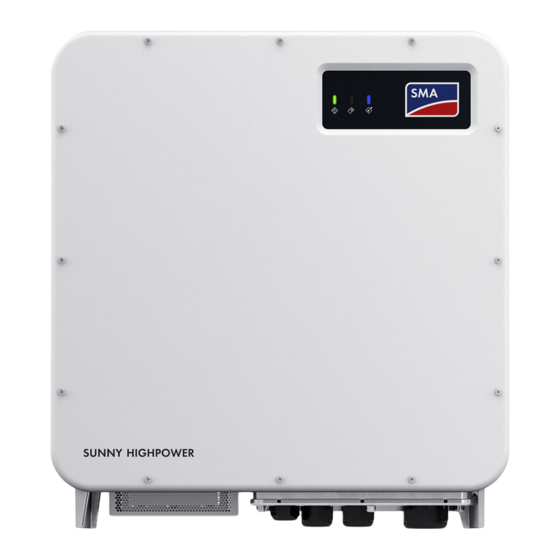
SMA Solar Technology AG 5 Product Overview Product Overview Product Description Figure 2: Design of the product Position Designation LEDs The LEDs indicate the operating state of the product. Type label The type label clearly identifies the product. The type label must remain permanently attached to the product. - Page 18 5 Product Overview SMA Solar Technology AG Symbol Explanation Beware of hot surface The product can get hot during operation. Observe the documentation Observe all documentation supplied with the product. Inverter Together with the green LED, this symbol indicates the operating state of the in- verter.
-
Page 19: Interfaces And Functions
The product is equipped with a Modbus interface. The Modbus interface is deactivated by default and must be configured as needed. The Modbus interface of the supported SMA products is designed for industrial use – via SCADA systems, for example – and has the following tasks: •... -
Page 20: Led Signals
5 Product Overview SMA Solar Technology AG SMA Smart Connected is activated during registration in Sunny Portal. In order to use SMA Smart Connected, it is necessary that the product is permanently connected to Sunny Portal and the data of the operator and qualified person is stored in Sunny Portal and up-to-date. -
Page 21: Mounting And Preparing The Connection
SMA Solar Technology AG 6 Mounting and Preparing the Connection Mounting and Preparing the Connection Requirements for Mounting Requirements for mounting location: WARNING Danger to life due to fire or explosion Despite careful construction, electrical devices can cause fires. This can result in death or serious injury. - Page 22 6 Mounting and Preparing the Connection SMA Solar Technology AG 40 − 60 (1.57 − 2.36) 767.5 (30.2) 700 (27.56) 770 (30.3) 450.6 (17.7) Figure 3: Dimensions of the profile rails and the clamping range of the mounting bracket (dimensions in mm (in)) Center of gravity: 8.4 (0.3)
-
Page 23: Connecting Plates Overview
SMA Solar Technology AG 6 Mounting and Preparing the Connection Permitted and prohibited mounting positions: ☐ The product may only be mounted in a permitted position. This will ensure that no moisture can penetrate the product. ☐ The product should be mounted such that the LED signals can be read off without difficulty. - Page 24 6 Mounting and Preparing the Connection SMA Solar Technology AG Standard connecting plate Position Designation Entry for network cable (M32) Entry for DC cable (M40) Entry for AC cable (M63) Optionally available connecting plate Position Designation Entry for network cable (M32)
-
Page 25: Mounting The Product And Preparing The Connection
SMA Solar Technology AG 6 Mounting and Preparing the Connection Mounting the Product and Preparing the Connection DANGER Danger to life due to electric shock when live cables are touched High voltages are present on the AC and DC cables. Touching live cables results in death or lethal injuries due to electric shock. - Page 26 6 Mounting and Preparing the Connection SMA Solar Technology AG 3. Fasten all four screws of each mounting bracket hand-tight (TX40). 4. Ensure the correct position of the mounting brackets by hooking in the mounting template. If the position is incorrect, move the mounting brackets to the correct position.
- Page 27 SMA Solar Technology AG 6 Mounting and Preparing the Connection 13. Screw the transport handles as far as they will go into the taps on the right- and left-hand side until they lie flush with the enclosure. When doing so, ensure that the transport handles are screwed into the taps so that they are perfectly straight.
- Page 28 6 Mounting and Preparing the Connection SMA Solar Technology AG 20. Secure the product with one screw each on the right and left on the mounting bracket (M8x16, TX40, 12 Nm ± 2 Nm). 21. Remove all four transport handles from the threaded holes.
-
Page 29: Electrical Connection
SMA Solar Technology AG 7 Electrical Connection Electrical Connection Overview of the Connection Area Figure 7: Connection areas in the interior of the product Position Designation Connection for additional grounding or equipotential bonding (optional) Cable for DC connection with tin-plated copper terminal lugs... -
Page 30: Ac Connection
If local regulations require the use of a residual-current device, the following must be observed: • The inverter is compatible with type B residual-current devices. For SHP 100-20 the rated residual current must be 1000 mA and for SHP 150-20 the rated residual current must be 1500 mA or higher (for information on selecting a residual-current device, see Technical Information "Criteria for Selecting a Residual-Current Device"... - Page 31 SMA Solar Technology AG 7 Electrical Connection Required material (not included in the scope of delivery): ☐ Protective grease (only for conductors made of aluminum) Procedure: 1. Ensure that the AC circuit breaker is switched off and that it cannot be reconnected.
-
Page 32: Connecting The Network Cables
7 Electrical Connection SMA Solar Technology AG Connecting the Network Cables DANGER Danger to life due to electric shock in case of overvoltages and if surge protection is missing Overvoltages (e. g. in the event of a flash of lightning) can be further conducted into the building and to other connected devices in the same network via the network cables or other data cables if there is no surge protection. - Page 33 SMA Solar Technology AG 7 Electrical Connection Laying the cables: Figure 8: Interior view of the product with laying plan for network cables Procedure: DANGER Danger to life due to electric shock • Disconnect the inverter from all voltage sources (see Section 10, page 56).
-
Page 34: Connecting The Pv Array
7 Electrical Connection SMA Solar Technology AG 6. Lead each cable through a cable gland in the connection plate up to the network jacks. Lay each cable according to the installation plan and attach to the brackets. 7. Put the RJ45 plug of the cable into one of the network sockets of the communication assembly. - Page 35 SMA Solar Technology AG 7 Electrical Connection Requirements: ☐ Depending on the design, one or two PV combiner boxes must be present. ☐ There must be an external DC load-break switch between the PV inverter and the PV array (e.g., a PV combiner box including a load-break switch).
- Page 36 7 Electrical Connection SMA Solar Technology AG 3. Fit terminal lugs to the DC conductors. 4. Remove any cable remnants from the product. 5. Remove the fixing of the pre-harnessed DC cables from the product. 6. Clean the contact surfaces of all terminal lugs using a clean cloth and ethanol cleaning agent and do not touch the contact surfaces after cleaning.
-
Page 37: Commissioning
When the inverter is captured in a communication device, the communication device (e.g. SMA Data Manager) is the unit for configuring the total system. The configuration is transferred to all inverters in the system. The system password assigned via the communication device is also the password for the user interface of the inverter. -
Page 38: Commissioning The Inverter
8 Commissioning SMA Solar Technology AG Commissioning the Inverter Requirements: ☐ A means of disconnecting the inverter from the PV array must be present. ☐ The AC circuit breaker must be correctly rated and mounted. ☐ The product must be correctly mounted. -
Page 39: Selecting A Configuration Option
On the Configuring the Inverter page, different configuration options are available to choose from. Select one of the options and proceed for the selected option as described below. SMA Solar Technology AG recommends carrying out the configuration with the installation assistant. This way, you ensure that all relevant parameters are set for optimal inverter operation. - Page 40 8 Commissioning SMA Solar Technology AG • Adoption of configuration from a file • Configuration with the installation assistant (recommended) • Manual configuration Accepting the settings Saving the made settings is indicated by an hourglass symbol on the user interface. If the DC voltage is sufficient, the data is transferred directly to the inverter and accepted.
- Page 41 SMA Solar Technology AG 8 Commissioning Procedure: 1. Select the configuration option Manual Configuration. ☑ The Device Parameters menu on the user interface will open and all available parameter groups of the inverter will be displayed. 2. Select [Edit parameters].
-
Page 42: Operation
☐ The respective latest version of one of the following web browsers must be installed: Chrome, Edge, Firefox, Internet Explorer or Safari. ☐ The SMA Grid Guard code of the Installer must be available for the changing of grid-relevant settings after completion of the first ten feed-in hours or installation assistant (see "Application for SMA Grid Guard Code"... -
Page 43: Establishing A Connection Via Ethernet In The Local Network
☐ The respective latest version of one of the following web browsers must be installed: Chrome, Edge, Firefox, Internet Explorer or Safari. ☐ The SMA Grid Guard code of the Installer must be available for the changing of grid-relevant settings after completion of the first ten feed-in hours or installation assistant (see "Application for SMA Grid Guard Code"... - Page 44 4. Click on Save. 5. In the New password field, enter a password for the Installer user group. Assign a uniform password to all SMA devices to be registered in a system. The installer password is also the system password.
- Page 45 SMA Solar Technology AG 9 Operation Log Out as the User or Installer 1. On the right-hand side of the menu bar, select the menu User Settings. 2. In the subsequent context menu, select [Logout]. ☑ The login page of the user interface opens. The logout was successful.
-
Page 46: Start Page Design Of The User Interface
9 Operation SMA Solar Technology AG Start Page Design of the User Interface Figure 11: Design of the user interface's start page (example) SHP-20-BE-en-12 Operating manual... - Page 47 • Starting the installation assistant • SMA Grid Guard login • Logout Help Provides the following functions: • Displaying information on Open Source licenses used • Link to the website of SMA Solar Technology AG Operating manual SHP-20-BE-en-12...
- Page 48 9 Operation SMA Solar Technology AG Position Designation Description Status bar Displays the following information: • Inverter serial number • Inverter firmware version • IP address of the inverter in the local network • User group logged in • Date and device time of the inverter...
-
Page 49: Starting The Installation Assistant
Requirement: ☐ When configuring after completion of the first ten feed-in hours or after exiting the installation assistant, the SMA Grid Guard code must be available in order to change the grid-relevant parameters (see "Application for SMA Grid Guard Code" at www.SMA-Solar.com). Procedure: 1. -
Page 50: Switching The Dynamic Power Display Off
This section describes the basic procedure for changing operating parameters. Always change operating parameters as described in this section. Some function-sensitive parameters can only be viewed by qualified persons and can only be changed by qualified persons by entering the personal SMA Grid Guard code. SHP-20-BE-en-12 Operating manual... -
Page 51: Configuring The Country Data Set
3. Call up the menu Device Parameters. 4. Click on [Edit parameters]. 5. Log in using the SMA Grid Guard code to change those parameters designated by a lock (only for installers): • Select the menu User Settings (see Section 9.3, page 46). -
Page 52: Configuring The Active Power Mode
9 Operation SMA Solar Technology AG Change to the names and units of grid parameters to comply with the grid- connection requirements in accordance with Regulation (EU) 2016/631 (valid from April 27, 2019) To comply with the EU grid-connection requirements (valid from April 27, 2019) the names and units of grid parameters were changed. -
Page 53: Configuring The Modbus Function
The Modbus interface is deactivated by default and the communication ports 502 set. ® ® ® In order to access SMA invertes with SMA Modbus or SunSpec Modbus , the Modbus interface must be activated. After activating the interface, the communication ports of both IP protocols can be changed. -
Page 54: Saving The Configuration In A File
Requirements: ☐ Changes to grid-relevant parameters must be approved by the responsible grid operator. ☐ The SMA Grid Guard code must be available (see "Application for SMA Grid Guard Code" at www.SMA-Solar.com). Procedure: 1. Open the user interface (see Section 9.1, page 42). - Page 55 Requirements: ☐ An update file with the desired inverter firmware must be available. The update file is, for example, available for download on the product page of the inverter at www.SMA-Solar.com. Procedure: 1. Open the user interface (see Section 9.1, page 42).
-
Page 56: Disconnecting The Inverter From Voltage Sources
10 Disconnecting the Inverter from Voltage Sources SMA Solar Technology AG 10 Disconnecting the Inverter from Voltage Sources Prior to performing any work on the inverter, always disconnect it from all voltage sources as described in this section. Always adhere to the prescribed sequence. - Page 57 SMA Solar Technology AG 10 Disconnecting the Inverter from Voltage Sources 8. Ensure that no voltage is present between the positive terminal and negative terminal on the DC surge protection devices using a suitable measuring device. To do so, insert the test probe (maximum diameter: 2.5 mm) into the measuring points of the...
-
Page 58: Clean The Product
11 Clean the product SMA Solar Technology AG 11 Clean the product NOTICE Damage to the product due to cleaning agents The use of cleaning agents may cause damage to the product and its components. • Clean the product and all its components only with a cloth moistened with clear water. -
Page 59: Troubleshooting
Installer is the same as the system password in the communication product. Procedure: 1. Request PUK (application form available at www.SMA-Solar.com). 2. Open the user interface (see Section 9.1, page 42). 3. Enter the PUK instead of the password into the field Password. -
Page 60: Event Messages
12 Troubleshooting SMA Solar Technology AG 12.2 Event Messages Event number Message, cause and corrective measures Grid fault The grid voltage or grid impedance at the connection point of the inverter is too high. The inverter has disconnected from the utility grid. - Page 61 SMA Solar Technology AG 12 Troubleshooting Event number Message, cause and corrective measures Active power limit AC voltage The inverter has reduced its power due to a too-high grid voltage to ensure grid stability. Corrective measures: • If possible, check the grid voltage and observe how often fluctuations occur.
- Page 62 12 Troubleshooting SMA Solar Technology AG Event number Message, cause and corrective measures Active power limit AC frequency The inverter has reduced its power due to a too-high power frequency to en- sure grid stability. Corrective measures: • If possible, check the power frequency and observe how often fluctuations occur.
- Page 63 SMA Solar Technology AG 12 Troubleshooting Event number Message, cause and corrective measures 1302 Waiting for grid voltage > Installation failure grid connection > Check grid and fuses L is not connected. Corrective measures: • Ensure that the line conductors are connected.
- Page 64 12 Troubleshooting SMA Solar Technology AG Event number Message, cause and corrective measures 3401 DC overvoltage > Disconnect generator Overvoltage at the DC input. This can destroy the inverter. This message is signalized additionally by rapid flashing of the LEDs.
- Page 65 SMA Solar Technology AG 12 Troubleshooting Event number Message, cause and corrective measures 3901 3902 Waiting for DC start conditions > Start conditions not met The feed-in conditions for the utility grid are not yet fulfilled. Corrective measures: • Ensure that the PV array is not covered by snow or otherwise shaded.
- Page 66 12 Troubleshooting SMA Solar Technology AG Event number Message, cause and corrective measures 6701 6702 Communication disturbed Error in the communication processor, the inverter continues feeding in, how- ever. The cause must be determined by the Service. Corrective measures: • If this message is displayed frequently, contact the Service.
- Page 67 SMA Solar Technology AG 12 Troubleshooting Event number Message, cause and corrective measures 7324 Wait for update conditions The testing of the update conditions was not successful. The firmware update package is not suitable for this inverter. Corrective measures: • Retry update.
- Page 68 12 Troubleshooting SMA Solar Technology AG Event number Message, cause and corrective measures 7348 Incorrect file format The configuration file is not of the required format or is damaged. Corrective measures: • Ensure that the selected configuration file is of the required format and is not damaged.
- Page 69 SMA Solar Technology AG 12 Troubleshooting Event number Message, cause and corrective measures 7801 Error overvoltage protector One or more surge arresters have tripped or one or more surge arresters are not inserted correctly. Corrective measures: • Make sure that the surge arrester is inserted correctly.
- Page 70 9003 Grid parameter locked Changes to the grid parameters are now blocked. In order to be able to make changes to the grid parameters, from now on you must log in using the SMA Grid Guard code. 9007 Abort self-test The self-test (Italy only) was terminated.
- Page 71 SMA Solar Technology AG 12 Troubleshooting Event number Message, cause and corrective measures 10109 Time adjusted / new time 10110 Time synchronization failed: |xx| No time information could be called up from the set NTP server. Corrective measures: • Ensure that the NTP server was configured correctly.
- Page 72 12 Troubleshooting SMA Solar Technology AG Event number Message, cause and corrective measures 10251 [Interface]: communication status goes to [OK / Warning / Error / Not connected] The communication status to the network switch or DHCP server (router) has changed. An additional error message may be displayed.
- Page 73 SMA Solar Technology AG 12 Troubleshooting Event number Message, cause and corrective measures 10255 [Interface]: Network load OK The network load has returned to a normal range after being busy. 10282 [User group]-Login via [protocol] locked After several incorrect login attempts, login has been blocked for a limited time.
- Page 74 12 Troubleshooting SMA Solar Technology AG Event number Message, cause and corrective measures 10903 Uac Max [xxx] V 10904 Uac Min [xxx] V 10905 Uac Min Fast [xxx] V 10906 Fac SwMax [xxx] Hz 10907 Fac SwMin [xxx] Hz 10908 Fac Max [xxx] Hz 10909 Fac Min [xxx] Hz 10910 Disconn.
-
Page 75: Checking The Pv System For Ground Faults
SMA Solar Technology AG 12 Troubleshooting 12.3 Checking the PV System for Ground Faults If the red LED is glowing and the event number 3501, 3601 or 3701 is being displayed in the Results menu on the inverter user interface, there may be a ground fault present. The electrical insulation from the PV system to ground is defective or insufficient. - Page 76 40 MOhm and for polycrystalline and monocrystalline PV modules approximately 50 MOhm per PV module (for further information on calculating the insulation resistance see the Technical Information "Insulation Resistance (Riso) of Non-Galvanically Isolated PV Systems" at www.SMA-Solar.com). Required devices: ☐ Suitable device for safe disconnection and short-circuiting ☐...
-
Page 77: Replacing The Surge Arrester
The following diagnostic functions are available: • Activate Speedwire communication display on the inverter • Test Speedwire communication via SMA Data Manager Activating the Speedwire Communication Display on the Inverter By activating this diagnostic function, the inverter can signal that one network cable is connected by the blue LED flashing. -
Page 78: Cleaning The Fans
Testing the Speedwire Communication via SMA Data Manager If there is a SMA Data Manager in the system, the inverter can indicate signal whether the Speedwire communication is working properly or if there is a problem by the red LED flashing. The diagnostic function can only be activated via the user interface of the SMA Data Manager. - Page 79 SMA Solar Technology AG 12 Troubleshooting 3. Move the fan bracket upwards and fold it backwards. Note that the fan bracket cannot be removed completely because it is connected to the inverter by the fan cable. NOTICE Damage to the fans due to compressed air •...
-
Page 80: Decommissioning The Inverter
13 Decommissioning the Inverter SMA Solar Technology AG 13 Decommissioning the Inverter To decommission the inverter completely upon completion of its service life, proceed as described in this Section. CAUTION Risk of injury due to weight of product Injuries may result if the product is lifted incorrectly or dropped while being transported or mounted. - Page 81 SMA Solar Technology AG 13 Decommissioning the Inverter 2. Remove the AC cable from the inverter. To do so, loosen the screws (AF8) and pull the cables out of the terminal. 3. Remove the AC cable from the inverter. 4. Remove the protection elements against contact from the terminal lugs for the DC connection.
- Page 82 13 Decommissioning the Inverter SMA Solar Technology AG 9. Dismantle the connecting plate. To do so, unscrew the three screws (TX40). 10. Position the enclosure lid and first tighten the upper- left and lower-right screws, and then the remaining screws crosswise (TX25, torque: 6 Nm ± 0.3 Nm).
- Page 83 SMA Solar Technology AG 13 Decommissioning the Inverter 15. Remove the inverter from the mounting lugs of the mounting brackets by moving it upward. 16. Remove all four transport handles from the threaded holes. If necessary, insert a screwdriver into the holes on the transport handle and use the screwdriver to remove the transport handle.
-
Page 84: Procedure For Receiving A Replacement Device
Under fault conditions, the product may need to be replaced. If this is the case, you will receive a replacement device from SMA Solar Technology AG. If you received a replacement device, replace the defective product with the replacement device as described below. - Page 85 11. Pack the defective product in the packaging of the replacement device. 12. Fasten the packaging to the pallet on which the replacement device was supplied using the reusable lashing straps. 13. Arrange for pick-up with SMA Solar Technology AG. Operating manual SHP-20-BE-en-12...
-
Page 86: Technical Data
15 Technical Data SMA Solar Technology AG 15 Technical Data DC input SHP 100-20 SHP 150-20 Maximum PV array power 150000 Wp 225000 Wp Maximum input voltage 1000 V 1500 V MPP voltage range 590 V to 1000 V 880 V to 1450 V Rated input voltage 590 V 880 V... - Page 87 Surge arrester type 2 DC surge protection Surge arrester type 2 AC short-circuit current capability Current control Grid monitoring SMA Grid Guard 10.0 Maximum overcurrent protection 250 A Ground-fault monitoring for SHP 100-20 Insulation monitoring: R > 33 kΩ Operating manual SHP-20-BE-en-12...
- Page 88 15 Technical Data SMA Solar Technology AG Ground-fault monitoring for SHP 150-20 Insulation monitoring: R > 50 kΩ All-pole sensitive residual-current monitoring unit Available General Data Width x height x depth 770 mm x 833 mm x 444 mm Weight with enclosure lid and connecting plate 98 kg...
- Page 89 SMA Solar Technology AG 15 Technical Data Threshold for relative humidity, non-condensing 100 % Extended air pressure range 79.5 kPa to 106 kPa Transport in accordance with IEC 60721-3-4, Class 2K3 Temperature range -40°C to +70°C Equipment DC terminal Terminal lugs AC terminal Screw terminals...
-
Page 90: Contact
16 Contact SMA Solar Technology AG 16 Contact If you have technical problems with our products, please contact the SMA Service Line. The following data is required in order to provide you with the necessary assistance: • Device type • Serial number •... - Page 91 Toll free for Australia: SMA Online Service Center: 1800 SMA AUS www.SMA-Service.com (1800 762 287) International: +61 2 9491 4200 United Arab SMA Middle East LLC India SMA Solar India Pvt. Ltd. Emirates Abu Dhabi Mumbai +971 2234 6177 +91 22 61713888 SMA Online Service Center: www.SMA-Service.com Operating manual SHP-20-BE-en-12...
- Page 92 16 Contact SMA Solar Technology AG ไทย Service Partner for String inverter: 대한민국 Enerone Technology Co., Ltd Solar Power Engineering Co., Ltd. 4th Fl, Jungbu Bldg, 329, 333/7,8,9 United Tower Build- Yeongdong-daero, Gangnam- ing 4th floor. Soi Sukhumvit 55 (Thonglor 17),...
-
Page 93: Eu Declaration Of Conformity
(L 174/88, June 8, 2011) and 2015/863/EU (L 137/10, March 31, 2015) (RoHS) SMA Solar Technology AG confirms herewith that the products described in this document are in compliance with the fundamental requirements and other relevant provisions of the above- mentioned directives. The entire EU Declaration of Conformity can be found at www.SMA- Solar.com. - Page 94 www.SMA-Solar.com...
Need help?
Do you have a question about the SHP 100-20 and is the answer not in the manual?
Questions and answers