
Related Manuals for Viconics VZ8250


Summary of Contents for Viconics VZ8250
- Page 1 VT8000 Room Controllers VZ8250 Installation Guide Variable Air Volume (VAV) Unit Version 2...
-
Page 2: Table Of Contents
TABLE OF CONTENTS SAFETY INFORMATION ..........................3 INSTALLATION .............................. 6 TYPICAL APPLICATION: PRESSURE INDEPENDENT (NO FAN) ..............7 TYPICAL APPLICATION: PRESSURE INDEPENDENT (PARALLEL FAN) ............8 TYPICAL APPLICATION: PRESSURE DEPENDENT (NO FAN) ..............9 TERMINAL IDENTIFICATION ........................10 HOME SCREEN DISPLAY ........................... 13 HOW TO ENTER SET-UP SCREEN ...................... -
Page 3: Safety Information
Electrical equipment should be installed, operated, serviced, and maintained only by qualified personnel. No responsibility is assumed by Viconics Technologies for any consequences arising out of the use of this material. A qualified person is one who has skills and knowledge related to the construction, installation, and operation of electrical equipment and has received safety training to recognize and avoid the hazards involved. - Page 4 VZ8250 Installation Guide BEFORE YOU BEGIN LOSS OF CONTROL WARNING LOSS OF CONTROL • The designer of any control scheme must consider the potential failure modes of control paths and, for certain critical control functions, provide a means to achieve a safe state during and after a path failure. Examples of critical control functions are emergency stop and over travel stop.
- Page 5 VZ8250 Installation Guide INSTALLATION NOTICE INSTALLATION • The system must be installed correctly by a qualified technician. • If replacing an existing Room Controller, label wires before removal of Controller. • Electronic controls are static sensitive devices. Discharge yourself correctly before manipulating and installing Room Controller.
-
Page 6: Installation
VZ8250 Installation Guide INSTALLATION Remove the security screw (if applicable) from the bottom of the Room Controller cover. Open the unit by pulling on the bottom side of the Room Controller (Figure 1). Read the FCC ID and IC label installed inside the cover before installing any wireless product. -
Page 7: Typical Application: Pressure Independent (No Fan)
Actuator type 0-10V DA Fan type None Reheat configuration Duct + baseboard Duct heater 0-10V DA Baseboard configuration PWM VAC Refer to the VZ8250 Application Guide for more information on the “Sequence of Operations and Wiring”. 028-0506-02_II-VZ8250_EN www.viconics.com January 2020... -
Page 8: Typical Application: Pressure Independent (Parallel Fan)
Actuator type 0-10V DA Fan type Parallel binary Reheat configuration Duct + baseboard Duct heater 0-10V DA Baseboard configuration PWM VAC Refer to the VZ8250 Application Guide for more information on the “Sequence of Operations and Wiring”. 028-0506-02_II-VZ8250_EN www.viconics.com January 2020... -
Page 9: Typical Application: Pressure Dependent (No Fan)
Actuator type Floating Fan type None Reheat configuration Duct + baseboard Duct heater Floating Baseboard configuration Valve NC (Normally Closed) Refer to the VZ8250 Application Guide for more information on the “Sequence of Operations and Wiring”. 028-0506-02_II-VZ8250_EN www.viconics.com January 2020... -
Page 10: Terminal Identification
VZ8250 Installation Guide TERMINAL IDENTIFICATION FAN TYPE Supported fan types: • Parallel On/Off • Serial On/Off • Parallel ECM • Serial ECM Supported output types: • On/Off: Binary Output • ECM: Analog Output Binary (24V~) Terminal Name Connection 24V~ Enable... - Page 11 VZ8250 Installation Guide DAMPER Supported output types: • 0-10V Direct Acting • 0-10V Reverse Acting • 2-10V Direct Acting • 2-10V Reverse Acting • Floating Recommended damper: Schneider Electric MS41-6043 or equivalent. 0-10V Analog Actuator Terminal Name Connection RC / 24 V~ Hot...
- Page 12 Valve NC, or UO12 24 V~ Output • Valve NO REHEAT - BASEBOARD The VZ8250 controls baseboard heaters via: • Relay = 4 CPH (Cycles Per Hour) • PWM = 10-second duty cycle • Valve (Normally Open or Normally Closed) = 8 CPH (Cycles Per Hour) Supported output types: •...
-
Page 13: Home Screen Display
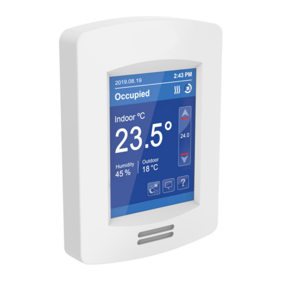
VZ8250 Installation Guide HOME SCREEN DISPLAY Hospitality User Interface Shown Date Time Occupancy Status System Status Up Arrow Raise Temperature Setpoint Room Indoor Temperature Actual Setpoint Down Arrow Room Indoor Humidity Lower Temperature Setpoint Outdoor Temperature Help Enter help screen... -
Page 14: How To Enter Set-Up Screen
S erv ice View Enter status and service view General Note: Adjustable parameter Nonadjustable parameter Return to home screen For more information on using and configuring the functions of the HMI, refer to the VZ8250 User Interface Guide. 028-0506-02_II-VZ8250_EN www.viconics.com January 2020... -
Page 15: 10. Balancing
True air flow will be measured and compared to the airflow calculated by the VZ8250 at various setpoints. ‚ VZ8250 calibration parameters will be adjusted by the technician to ensure the calculated air flow matches the true air flow. ‚... - Page 16 VZ8250 Installation Guide The recommended process for Balancing the system is: On page “1/2 Balancing (PI)”, check the Minimum, Maximum Cooling, Maximum Heating and Reheat airflow setpoints are correctly configured for the zone. Check airflow sensor is correctly zeroed: On page “2/2 Balancing (PI)”, set Damper Override to Close.
- Page 17 VZ8250 Installation Guide BALANCING OPTIONS 1/2 Balanc ing (PI ) A irflow level 4 9 CF M 50 CF M A irflow setpoin t Min . f low 50 C FM Ma x . coo l flow 18 0 CF M Ma x .
- Page 18 VZ8250 Installation Guide 2/2 Balanc ing (PI ) A irflow level 4 9 CF M 50 CF M A irflow setpoin t D am p. o verride Mi n. fl o w B alo me ter 50 C FM Min . f low o ffset...
- Page 19 VZ8250 Installation Guide 10.2 PRESSURE DEPENDENT Before starting to Balance the system, check the following parameters are correctly configured in the Configuration menu: • VAV Box Type • Actuator Type • Floating Actuator Time Air Flow Balancing settings can be found on the Balancing page of the Setup menu.
- Page 20 VZ8250 Installation Guide Pressure Independent Configuration parameter BACnet Function description Maximum Heating Position AV252 (R/W) Maximum damper position during heating: • Units = % • Min = 0 • Max = 100 Reheat Position AV253 (R/W) Damper position during reheating: •...
-
Page 21: Appendix A. Deployment
VZ8250 Installation Guide APPENDIX A. DEPLOYMENT Placement of the Room Controller must be given consideration. It is recommended to install the Room Controller as close to a door as possible (but not so as to be blocked by the door), or in an area with high occupant movement. - Page 22 VZ8250 Installation Guide EXAMPLE OF NON-RECOMMENDED DEPLOYMENT The below shows four Room Controllers (two for each room) installed in non-ideal locations for the two rooms. The examination room shows one Room Controller installed in a low traffic area near the door, and a second Room Controller installed on the wall directly opposite the door.
- Page 23 VZ8250 Installation Guide ROOM CONTROLER PIR SENSOR DETAILS The internal Room Controller PIR sensor only detect lateral movement. It cannot detect movement when a person is moving toward it. It will not detect someone seating on a chair and/or lying on the bed.
- Page 24 VZ8250 Installation Guide Install additional motion sensor in the bathroom. Install additional motion sensor for better motion detection in the entire room. ENERGY SAVINGS PIR can maximize your energy saving from 10-30% by adjusting temperature set points in unoccupied zones during scheduled periods.
Need help?
Do you have a question about the VZ8250 and is the answer not in the manual?
Questions and answers