Table of Contents
Advertisement
1. SPECIFICATIONS .........................................................................................................................
2-l Caution When Installing .........................................................................................................
2-2 Caution When Handling .........................................................................................................
3. INSPECTION.. ...............................................................................................................................
4 - l Game Components ..............................................................................................................
4-2 Installing Control Panel.. ........................................................................................................
4-3 Attaching Seat Assy. to Monitor Cabinet ...............................................................................
5 - l Power On.. .............................................................................................................................
5-3 Test Mode and Play Options .................................................................................................
5-3-3 Changing Game Settings (Game Option Screen) ....................................................
5-4 Test Screens .........................................................................................................................
5-5 Gun Adjustment ....................................................................................................................
5-6 Initializing Controls ..............................................................................................................
5-7 Monitor Adjustment ..............................................................................................................
7 - l Replacing Gun Assembly ....................................................................................................
7-2 Replacing Fluorescent Lamp ...............................................................................................
7-3 Opening Control Panel ........................................................................................................
Replacing Steering Assy. .......................................................................................
7-5 Brake & Accelerator Pedal Assembly.. ................................................................................
Replacing Pedal Assy. ............................................................................................
7-5-2 Replacing Pedal Potentiometer ..............................................................................
9. PARTS LIST ..........................................................................................................................
CONTENTS
1
2
2
4
4
5
6
6
8
10
12
13
14
14
15
15
15
16
16
16
18
26
Advertisement
Table of Contents

Related Manuals for NAMCO LUCKY & WILD


Summary of Contents for NAMCO LUCKY & WILD
-
Page 1: Table Of Contents
CONTENTS 1. SPECIFICATIONS ......................... 2. PRECAUTIONS 2-l Caution When Installing ......................2-2 Caution When Handling ......................3. INSPECTION..........................4. INSTALLATION 4 - l Game Components ......................4-2 Installing Control Panel......................4-3 Attaching Seat Assy. to Monitor Cabinet ................5. - Page 2 1 I LIST OF ILLUSTRATIONS 4 - t 3/4 Front and Back View of Game .,.,..,..______................ 4-2 Joining Seat Assembly to Cabinet ..................5-2 Game Option Screen ......................Switch Test Screen ........................ 5-5 Switch Test Description Table ....................Replacing Gun Assembly ....................7-2 Replacing Fluorescent Lamp ....................
-
Page 3: Specifications
Instruction Manual .._..........1 Note: Specifications may change without prior notice. Modification and/or alteration of the LUCKY & WILDTM game with kits or parts not supplied by NAMCO may void the warranty. PRECAUTIONS Cautions When Installing This game is designed for indoor use only. The game must not be installed out- doors or under the following conditions: a. -
Page 4: Caution When Handling
2-2 Caution When Handling AC power must always be turned OFF, and the game unplugged, before replacing any parts or connecting/disconnecting connectors. When unplugging the game from an elecaical outlet, always grasp the plug, not the cord. Do not subject game to physical shock when transporting or moving it. The power supply range is between 1 IO-120VAC, (switchable to 220 VAC). -
Page 5: Installation
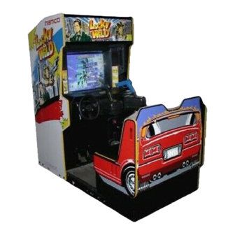
4. INSTALLATION 4-l Game Components FRONT and BACK VIEW OF GAME Illustration 4-1,314... -
Page 6: Installing Control Panel
4-2 Installing the Control Panel Assembly Remove the control panel from its carton. Insert the three (3) preinstalled bolts (studs) of the control panel hinge through the holes on the lower of the two control panel shelves on the monitor cabinet. Place three (3) nuts onto the hinge bolts and tighten to secure the conuol panel assembly to the lower conool panel shelf of the cabinet. -
Page 7: Adjustments 5-L Power On
5. ADJUSTMENTS 5-l Power on When installation is complete, connect the power cord to an AC outlet and turn the power on. The Power on/off Switch is located on the lower right side of the back of the cabinet. 5-2 Adjustment switches on the Service Panel The Service Panel is located behind the coin door. -
Page 8: Test Mode And Play Options
5-3 Test Mode The self-test function is activated by using the test switch, which also displays the Game Option Screen where the game pricing is changed. Additionally, there are 1. Self-test Open the coin door and move the test switch to the “ON” position. The “Game Option”... -
Page 9: Table Of Game Option Settings (Game Fee Example)
a. Selecting Item to Change Select an item to be changed by turning the steering wheel until the desired item is illuminated in red letters. Select the settings according to rhe TABLE OF GAME OPTION SETTINGS (below). b. Changing Settings To change the content of the selected item, squeeze the trigger of the left gun (driver’s side - 1P). -
Page 10: Test Screens
1. Switch Test Screen This test displays the status of the option switches on the game PC board (CPU-PCS). Any number displayed in RED. indicates it is turned ‘ON’. (b) TEST SW If ‘ON’ is displayed in RED, the condiiion is normal. ‘ON’... -
Page 11: Gun Adjustment
5-5 Gun Adjustments For normal game play, the guns must be adjusted whenever replacing the game PCB, gun assembly or potentiometers, by following the procedure described below: 1. Open the coin door. 2. Set the test switch to “ON”. Press the service switch several times until Screen 1 (below) is displayed. -
Page 12: Initializing Controls
5-6 Initializing Controls When replacing the game PCB, the Steering Assembly, the Gas Pedal and Brake Assembly, or the potentiometers, be sure to follow the procedures below. Open the coin door. Remove hands and feet from the steering wheel, accelerator pedal and brake With the game screen displayed on the monitor screen, set the test switch to “ON”... -
Page 13: Monitor Adjustment
5-7 Monitor Adjustment The monitor remote adjustment conuol is located by opening the control panel. VR 102 VR 101 VR 103 VR 105 VR 106 VR 104 ROW. LEFTTO RIGKT BOTTOM ROW - LEFTTO RIGHT VR 103 -VERTICAL POSITION VR 106. HORIZONTAL POSITION VR 105 VERTICAL HOLD VR 102 - BLACK LEVEL VR 101 -CONTRAST... -
Page 14: Howto Play
6. HOW TO PLAY LUCKY & WILD is a game that allows one or two players to shoot and destroy enemies that emerge on the screen by operating the steering wheel, the accelerator and the brake. The left (IP) player operates the steering wheel, the accelerator, the brake and the left gun. -
Page 15: Maintenance
MAINTENANCE CAUTION POWER BEFORE CONDUCTING ANY MAINTENANCE PROCEDURES 7 - l Replacing the Gun Assembly base covers (L) and (R). Carefully pull the fwo covers apart to remove. Remove the two (2) cap screw bolts (M5 x 12) that secure the cover holder to the gun on the side opposite the gun base. -
Page 16: Replacing Fluorescent Lamp
7-2 Replacing the Fluorescent Lamp 1. Remove the four (4) bolts securing the upper marquee bracket to the top of the game cabinet. bolts on 2. Loosen, but don’t remove the four (4) the lower marquee bracket. 3. Remove the upper bracket, and remove the marquee panel by sliding up and out. -
Page 17: 7-T Steering Assembly
7-4 Steering Assembly NOTE: LUCKY & WILD uses a HAPP CONTROLS steering mechanism. NOTE: Numbers shown are Happ Controls Part Numbers. 7-3. RAPP STEERING ASSEMBLY Illustration 741 Replacing the Steering Assembly (1) Remove the steering wheel by taking off the center cap and removing the three (3) bolts. -
Page 18: Brake & Accelerator Pedal Assembly
7-5 Brake & Accelerator Pedal Assembly NOTE: LUCKY & WILD uses HAPP CONTROLS mechanism. pedal NOTE: Numbers shown are Happ Controls Part Numbers. Illustration 74, HAPP DUAL PEDAL ASSEMBLY 7-5-l Replacing the Brake & Accelerator Pedal Assembly (1) Open the mar door and remove the connector to the pedal assembly. (2) The Pedal Assembly may now be removed from the front. -
Page 19: Removing The Game Pcs
CAUTION Be sure to unplug the AC power before conducting the following procedure Disconnect the two connectors from the EMI board. Remove the two (2) mounting screws securing the EM&PC board to the PC board case. Gently pull the EM.-PC board and the game PC board out to remove. The entire PC game case may be removed after step 2, if required, by remov- ing one (1) mounting screw securing the case to the back board to which it is attached, and carefully lifting it out. -
Page 20: Troubleshooting -General
TROUBLESHOOTING - GENERAL If you suspect the game may be malfunctioning, the following steps should be taken before you make a service request. (1) Check to see that the circuit breaker is properly set. (2) The power supply should be set to either 110 or 220 Volts AC. However, when some other equipment (air conditioner, multiple pinball games, air compressors, etc.) are connected to the same power supply, the voltage may change beyond this range and cause game trouble or improper operation. - Page 21 COIN CONTROLS COIN DOOR ASSEMBLY...
-
Page 22: Parts List
Parts List... - Page 23 9. GUN ASSEMBLY...
- Page 24 9. PARTS (cont.)
- Page 25 LUCKY & WILDM WIRING DIAGRAM...
Need help?
Do you have a question about the LUCKY & WILD and is the answer not in the manual?
Questions and answers