Table of Contents
Advertisement
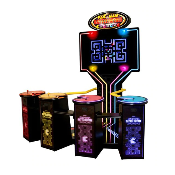
PAC-MAN BATTLE ROYALE DELUXE
OPERATION MANUAL
The actual product may differ slightly from the illustrations in this manual.
WARNING
To ensure safe operation of the game machine, be sure to read this Operation Manual before use.
Keep this Operation Manual in a safe place for quick access whenever needed.
Advertisement
Table of Contents

Related Manuals for NAMCO PAC-MAN BATTLE ROYALE DELUXE


Summary of Contents for NAMCO PAC-MAN BATTLE ROYALE DELUXE
- Page 1 PAC-MAN BATTLE ROYALE DELUXE OPERATION MANUAL The actual product may differ slightly from the illustrations in this manual. WARNING To ensure safe operation of the game machine, be sure to read this Operation Manual before use. Keep this Operation Manual in a safe place for quick access whenever needed.
- Page 2 No part of this publication may be reproduced by any mechanical photographic, or electronic process, or in the form of a photographic recording, nor may it be stored in a retrieval system, transmitted, or otherwise copied for public or private use, without permission from NAMCO AMERICA INC.
- Page 3 INTRODUCTION Thank you for purchasing the “PAC-MAN BATTLE ROYALE” game machine (hereinafter referred to as the “machine”). This operation manual describes: ● How to install, operate, relocate, transport, service, and discard the machine safely and properly ● How to operate the machine correctly and make full use of its features ●...
- Page 4 INTRODUCTION NOTES...
-
Page 5: Safety Precautions
1. SAFETY PRECAUTIONS – Be sure to read this section before installing or operating the machine. – Instructions to the owner z z Ifz youz entrustz anotherz partyz toz performz installation,z operation,z relocation,z transportation,z service,z orz discardingz ofz thez machine,z instructz thez concernedz partyz toz readz andz observez allz thez instructionsz andz precautionsz inz thisz operationz manualz regardingzthezparticularzactionztozbeztaken. -
Page 6: Critical Safety Precautions
1. SAFETY PRECAUTIONS 1-3 Critical safety precautions WARNING z Should any abnormality occur, turn off the power switch immediately to stop operating the machine. Then, unplug the power cord plug from the AC outlet. Operating the machine without correcting abnormalities can result in a fire or accident. -
Page 7: Description Of Warning Labels Attached To The Machine
1. SAFETY PRECAUTIONS 1-4 Description of warning labels attached to the machine WARNING z The warning labels describe important safety precautions. Be sure to observe the following: • To ensure that the warning labels attached to the machine are easily legible, install the machine at an appropriate location with ample illumination and keep the labels clean at all times. -
Page 8: Table Of Contents
CONTENTS INTRODUCTION 1. SAFETY PRECAUTIONS – Be sure to read this section before installing or operating the machine. – ..............1 1-1 Magnitudes of risk............................1 1-2 Definition of “technician” ..........................1 1-3 Critical safety precautions..........................2 1-4 Description of warning labels attached to the machine .................. 3 2. SPECIFICATIONS ............................6 3. PACKAGE CONTENTS ..........................8 4. - Page 9 CONTENTS 8A. ASSEMBLY AND SETUP – To be conducted by a technician only – ...............36 8A-1 Assembly ..............................36 8A-1-1 Securing the machine using level adjusters ..................36 8A-1-2 Removing and attaching the side service door ..................36 8A-1-3 Assembling the PACMAN BATTLE ROYALE DELUXE ..............37 8B. SERVICES – To be conducted by a technician only – ....................44 8B-1 Inspections and services ..........................44 8B-1-1 Inspection items .
-
Page 10: Specifications
2. SPECIFICATIONS (1) Rated power supply: US 120 ± 10% V AC (60 Hz) - UK 240 + 10% VAC (50Hz)60 (2) Maximum power consumption: 600W (3) Maximum current consumption: 5 A (120 V AC power supply) 2.5 A (240 V AC power supply) (4) Coin box capacity: Approx. - Page 11 2. SPECIFICATIONS Top View Cabinet: 95 x 86 x 115 in. (2,413 x 2,184 x 2,921 mm) (W x D x H) 60” 95 “ Front View Cabinet: 95 “...
-
Page 12: Package Contents
3. PACKAGE CONTENTS The product packages shipped from the factory contain the following components and parts. Make sure that all the items listed below (except the service key) are contained in the coin box. If any item is missing, contact your distributor. ... -
Page 13: Overall Construction (Names Of Parts)
4. OVERALL CONSTRUCTION (Names of Parts) Front Marquee Fluorescent lamps (inside) Fuse(5A 250V) Control Panel assembly (1P, Red) Control Panel assembly (2P, Yellow) Cord box Bill acceptor (option) X4 Power switch Coin Acceptor Control Panel assembly (3P, Pink) Control Panel assembly (4P, Blue) -
Page 14: Installation
5. INSTALLATION WARNING z Install the machine according to the instructions and procedures specified in this operation manual. Failure to follow the specified procedures may result in a fire, electric shock, injury or machine malfunctions. z Insert the power cord plug firmly into the AC outlet. Poor contact may cause overheating that can lead to a fire or burns. -
Page 15: Play Zone For Installed Machine
5. INSTALLATION 5-1-2 Play zone for installed machine WARNING z Create a play zone around the machine (space as shown below) to prevent players coming into contact with bystanders or passers-by. z The distance from the floor to the ceiling must be at least 10.6 ft. (3 m 23 cm). -
Page 16: Moving And Transporting
6. MOVING AND TRANSPORTING WARNING z Do not leave the machine on a slope. If the machine is left on a slope, it may tip over and cause an accident. 6-1 Moving (on the floor) z Carefully transport the machine so as not to cause excessive impacts to it, as the LCD monitor is a precision electronic component. -
Page 17: Transportation
6. MOVING AND TRANSPORTING 6-2 Transportation 6-2-1 Manual transportation (carrying on stairs, etc.) WARNING z When moving, always separate the machine into parts. (See P. 11 “5-2 Required dimensions for bringing the machine inside (such as doors and corridors).”) z When carrying the machine manually, the following number of people are needed. Attempting to carry the machine with fewer people can result in an accident or injury. -
Page 18: Operation
7. OPERATION WARNING z Some monitor sections remain hot or charged with high voltage even after the power switch is turned off. Do not touch the monitor unnecessarily in order to avoid electric shock and burns. z Dust accumulated on the power cord plug may cause a fire. Check the power cord plug regularly and remove dust. -
Page 19: Pre-Service Check
7. OPERATION 7-1 Pre-service check 7-1-1 Safety check (before power ON) WARNING z To prevent accidents and injury, be sure to conduct the pre-service check described below before commencing operation. (1) Are all warning indications in place? (See P. 3 “1-4 Description of warning labels attached to the machine.”) (2) Are the warning indications legible? (See P. 3 “1-4 Description of warning labels attached to the machine.”) (3) Are all level adjusters adjusted properly? (See P. 36 “8A-1-1 Securing the machine using level adjusters.”) -
Page 20: Operation Check (After Power On)
7. OPERATION 7-1-2 Operation check (after power ON) Check the following items in Test mode. (See P. 18 “7-2-2 Adjustment switches and but- tons.”) (1) Check the lamps for proper operation. (Do the fluorescent bulb and Start buttons light?) (See P. 25 “7-4-4 Switch/sensor test (I/O TEST).”) (2) Check the Start buttons for proper operation. (See P. 25 “7-4-4 Switch/sensor test (I/O TEST).”) (3) Check the displayed image. (Does the monitor show images properly?) (See P. 28 “7-4-5 Monitor condition (MONITOR TEST).”) (4) Check the sound. (Is sound produced by each loudspeaker?) (See P. 29 “7-4-6 Sound adjustment (SOUND TEST).”) (5) Check the clock. (See P. 33 “7-4-8 (1) CLOCK SETTING.”) -
Page 21: Explanation Of The Power Switch And Adjustment Switches
7. OPERATION 7-2 Explanation of the power switch and adjustment switches 7-2-1 Turning the power switch on Power switch z Be sure to complete the installation and setup of the machine before turning the power switch on. z When turning the power switch on or off, wait at least 30 seconds between switch operations. -
Page 22: Adjustment Switches And Buttons
7. OPERATION 7-2-2 Adjustment switches and buttons Open the service door on the first player station to gain access to the adjustment switches and buttons. Test switch Select switch Service button Enter button Test switch Set this switch to ON to activate Test mode. Test mode is used to test the monitor and other parts. (See P. 21 “7-4 Test mode.”) Service button (red) Press this button to increase the credit count without activating the coin counter. Enter button (green) After selecting an item or setting (a numeric value) using the Select switch, press this button to enter or execute the selection. -
Page 23: How To Play Pac-Man Battle Royale
7. OPERATION 7-3 How to play PAC-MAN BATTLE ROYALE 7-3-1 Game rules z Up to four players can battle together. z If your Pac-Man has eaten a power pellet, he can eat other players’ Pac-Men. z The last one standing wins the round. z Multiple rounds can be played per battle royale. 7-3-2 How to control your Pac-Man Move your Pac-Man through the maze by moving your joystick up, down, left, and right. 7-3-3 Items and a strategy in the maze Pac-dot The pac-dot pattern is refreshed when all pac-dots have been eaten. Food The pac-dot pattern is refreshed when food is eaten, even if some pac-dots remain. Power pellet When a Pac-Man eats a power pellet, he grows larger and other Pac-Men turn blue. -
Page 24: Start Button
7. OPERATION 7-3-4 START button z If any credits remain when you press the START button, you can start playing the game. z When you press the START button during a game in progress (group play), you (a maximum of four players) can participate in the first available round of play. (Note that this function is not available during the final round or in single mode.) z When you (winner or loser) press the START button during intermission (while Winner is displayed), you can throw paint bombs at the loser (for winner) or winner (for loser) to taunt your opponent(s). -
Page 25: Test Mode
7. OPERATION 7-4 Test mode 7-4-1 Description of the menu screen (MENU) Unlock the service door on the first player station and set the Test switch to ON. (See P. 18 “7-2-2 Adjustment switches and buttons.”) The Menu screen appears on the monitor. Game fee settings, etc. MENU See section 7-4-2 Game detail settings COIN OPTIONS See section 7-4-3 GAME OPTIONS I/O TEST Switch/button/joystick testing, etc. See section 7-4-4 MONITOR TEST SOUND TEST Monitor testing BOOKKEEPING See section 7-4-5 OTHERS Sound adjustment, etc. See section 7-4-6 Bookkeeping check CURRENT STATUS See section 7-4-7 BALANCE $1.00... -
Page 26: Game Fee Settings (Coin Options)
7. OPERATION 7-4-2 Game fee settings (COIN OPTIONS) This screen is used to set the game fee, free play, and other options. Select “COIN OPTIONS” in the Menu screen and press the Enter button. (See P. 21 “7-4-1 Description of the menu screen (MENU).”) The Coin Options screen appears on the monitor. COIN OPTIONS DEFAULT IN GREEN GAME COST $2.00 FREE PLAY PLAY TYPE GROUP CURRENCY DOLLAR VALUE OF MECHANICAL COUNT $0.25 VALUE OF COIN 1 $0.25... - Page 27 7. OPERATION Item Description Factory settings Sets the incremental value of the coin counter The value range varies depending on the currency. DOLLAR: $ 0.25 (fixed value) (e) V ALUE OF POUND: £ 0.10/£ 0.20/£ 0.50/£ 1/£ 20 MECHANICAL $ 0.25 EURO: € 0.10/€ 0.20/€ 0.50/€ 1/€ 20 COUNT COIN: 1 (fixed value) Each time the service button is pressed, the preset credit value increases in increments. Sets the pulse input weighting for a coin selector or bill acceptor connected to COIN UNIT 1 (As the input pulse value varies depending on the connected equipment, be sure to set the appropriate value.) The value range differs depending on the currency. DOLLAR: $ 0.25 to $ 25.0 (f) VALUE OF COIN 1 POUND: £ 0.10 to £ 10.0 (Settings for VALUE OF £ 0.20 to £ 20.0 COIN 2 and VALUE OF $ 0.25 £ 0.50 to £ 50.0 COIN 3/BILL PULSE are £ 1 to £ 100 the same.)
-
Page 28: Game Detail Settings (Game Options)
7. OPERATION 7-4-3 Game detail settings (GAME OPTIONS) This screen is used to set the game details. Select “GAME OPTIONS” in the Menu screen and press the Enter button. (See P. 21 “7-4-1 Description of the menu screen (MENU).”) The Game Options screen appears on the monitor. GAME OPTIONS DEFAULT IN GREEN GAME SPEED NORMAL ROUND NUMBERS TIME OUT NORMAL EXIT SELECT SW:CHOOSE ENTER SW:ENTER Game Options screen Item Description Factory settings Sets the game speed (a) GAME SPEED NORMAL FAST/NORMAL/SLOW Sets the available round number. -
Page 29: Switch/Sensor Test (I/O Test)
7. OPERATION 7-4-4 Switch/sensor test (I/O TEST) This screen is used to test the functions of the switches on the machine. Select “I/O TEST” in the Menu screen and press the Enter button. (See P. 21 “7-4-1 Description of the menu screen (MENU).”) The I/O Test screen appears on the monitor. I/O TEST DEFAULT IN GREEN SWITCH TEST OUTPUT TEST EXIT I/O PCB:CONNECT OK A. I. PCB:CONNECT OK SELECT SW:CHOOSE ENTER SW:ENTER I/O Test screen Item Description Proceeds to the Switch Test screen (a) SWITCH TEST (See P. 26 “7-4-4 (1) SWITCH TEST.”) Proceeds to the Output Test screen (b) OUTPUT TEST (See P. 27 “7-4-4 (2) OUTPUT TEST.”) -
Page 30: Switch Test
7. OPERATION (1) SWITCH TEST This screen is used to test the respective switch functions. Select “SWITCH TEST” in the “I/O TEST” screen and press the Enter button. (See P. 25 “7-4-4 Switch/sensor test (I/O TEST).”) The Switch Test screen appears on the monitor. SWITCH TEST ON:RED o + o o + o o + o o + o COIN1 COIN2 COIN3 SERVICE TEST SELECT (UP/DOWN) OFF/OFF ENTER UP SELECT SW + ENTER : EXIT Switch Test screen Item Description... -
Page 31: Output Test
7. OPERATION (2) OUTPUT TEST This screen is used to test the illuminated switches. Select “OUTPUT TEST” in the “I/O TEST” screen and press the Enter button. (See P. 25 “7-4-4 Switch/sensor test (I/O TEST).”) The Output Test screen appears on the monitor. OUTPUT TEST ON:RED LAMP1 LAMP2 LAMP3 LAMP4 EXIT SELECT SW:CHOOSE ENTER SW:ENTER Output Test screen Item Description (a) LAMP1 When this item is set to “ON,” the 1P Start button lights. (b) LAMP2 When this item is set to “ON,” the 2P Start button lights. (c) LAMP3 When this item is set to “ON,” the 3P Start button lights. (d) LAMP4 When this item is set to “ON,” the 4P Start button lights. Flip the Select switch up or down to select an item. The selected item will blink. Press the Enter button to enter the selection. Flip the Select switch to turn on the illuminated switch corresponding to the selected item. -
Page 32: Monitor Condition Test (Monitor Test)
7. OPERATION 7-4-5 Monitor condition test (MONITOR TEST) This screen is used to check the monitor. Select “MONITOR TEST” in the Menu screen and press the Enter button. (See P. 21 “7-4-1 Description of the menu screen (MENU).”) The Monitor Test screen appears on the monitor. MONITOR TEST GRADATION PATTERN CROSSHATCH PATTERN FULL WHITE EXIT SELECT SW:CHOOSE ENTER SW:ENTER Monitor Test screen Item Description (a) GRADATION PATTERN Displays a 16-step gradation pattern. (b) CROSSHATCH PATTERN Displays a crosshatch pattern. (c) FULL WHITE Displays an all-white screen. Flip the Select switch up or down to select an item. The selected item will blink. Press the Enter button to go to the screen under the selection. Press the Enter button again to return to the Monitor Test screen. To return to the Menu screen, select “EXIT” and press the Enter button. -
Page 33: Sound Adjustment (Sound Test)
7. OPERATION 7-4-6 Sound adjustment (SOUND TEST) This screen is used to adjust the sound volume, L/R channel balance, and other items. Select “SOUND TEST” in the Menu screen and press the Enter button. (See P. 21 “7-4-1 Description of the menu screen (MENU).”) The Sound Test screen appears on the monitor. SOUND TEST DEFAULT IN GREEN VOLUME GAME (0~15) ATTRACT (0~15) REQUEST NO. LR CHECK EXIT SELECT SW:CHOOSE ENTER SW:ENTER SERVICE SW:REQUEST ON/OFF Sound Test screen Item Description Factory settings Sets the sound volume in Game mode. -
Page 34: Game Data Display/Initialization (Bookkeeping)
7. OPERATION 7-4-7 Game data display/initialization (BOOKKEEPING) This screen is used to display various game data. Select “BOOK KEEPING” in the Menu screen and press the Enter button. (See P. 21 “7-4-1 Description of the menu screen (MENU).”) The Bookkeeping screen appears on the monitor. BOOKKEEPING POWER ON TIME 0:13 ‘20 TOTAL PLAY TIME 0:00 ‘10 AVE. PLAY TIME 0:00 ‘00 PLAY ON RATIO 0.0% PLAY COUNT COIN COUNT SERVICE SW COUNT NEXT ERROR LOG BOOKKEEPING INITIALIZE EXIT SELECT SW:CHOOSE... -
Page 35: Error Log
7. OPERATION (1) ERROR LOG This screen is used to check error logs. Select “ERROR LOG” in the Bookkeeping screen and press the Enter button. (See P. 30 “7-4-7 Game data display/initialization (BOOKKEEPING).”) The Error Log screen appears on the monitor. ERROR LOG 1/2 01 COIN ERROR1 JAN/01/2010 FRI 10:09 02 COIN ERROR1 JAN/01/2010 FRI 10:08 03 COIN ERROR1 JAN/01/2010 FRI 10:07 04 COIN ERROR1 JAN/01/2010 FRI 10:06 05 COIN ERROR1 JAN/01/2010 FRI 10:05 06 COIN ERROR1 JAN/01/2010 FRI 10:04 07 COIN ERROR1... -
Page 36: Initialization And Other Settings (Others)
7. OPERATION 7-4-8 Initialization and other settings (OTHERS) This screen is used to initialize bookkeeping data (BOOKKEEPING) and other items. Select “OTHERS” in the Menu screen and press the Enter button. (See P. 21 “7-4-1 Description of the menu screen (MENU).”) The Others screen appears on the monitor. OTHERS DATA PBR100-2-NA-MPRO-A57 MAY/26/2010 WED 20:40:54 CLOCK JUN/23/2010 WED 14:06:24 000000-000711 LANGUAGE CLOCK SETTING BACKUP MEMORY INITIALIZE EXIT SELECT SW:CHOOSE ENTER SW:ENTER Others screen Item Description (a) DATA Shows the version information. (b) CLOCK Shows the date and time. -
Page 37: Clock Setting
7. OPERATION (1) CLOCK SETTING This screen is used to adjust the internal clock. Select “CLOCK SETTING” in the Others screen and press the Enter button. (See P. 32 “7-4-8 Initialization and other settings (OTHERS).”) The Clock Setting screen appears on the monitor. CLOCK SETTING CURRENT TIME: JAN/01/2010 FRI 10:00:00 CHANGE TO: JAN/01/2010 FRI 10:00 EXIT SELECT SW:CHOOSE ENTER SW:ENTER Clock Setting screen Item Description (a) CURRENT TIME Shows the current time. (b) CHANGE TO: Sets the time. (c) SET Enters the change. Flip the Select switch up or down to select an item. The selected item will blink. Press the Enter button to enter the selection. Flip the Select switch up or down to change the setting, and then press the Enter button to enter the change. The display returns to the previous selection screen. -
Page 38: Backup Memory Initialize
7. OPERATION (2) BACKUP MEMORY INITIALIZE This screen is used to initialize the backup memory. Select “BACKUP MEMORY INITIALIZE” in the Others screen and press the Enter button. (See P. 32 “7-4-8 Initialization and other settings (OTHERS).”) The YES/NO option appears next to the selection. Select the YES option to initialize the backup memory. When initialization is complete, “COMPLETE!” appears on the screen. BACKUP MEMORY INITIALIZE? BACKUP MEMORY INITIALIZE COMPLETE! To return to the Others screen, select “EXIT” and press the Enter button. -
Page 39: Error Display (For The Arcade Operator)
7. OPERATION 7-5 Error display (for the arcade operator) z The following shows items to be checked by the arcade operator. If an error other than the following is encountered, request a technician for service. (Technicians, see P. 48 “8B-3 Error display (for the technician).”) Error code Error indication... -
Page 40: Assembly And Setup
8A. ASSEMBLY AND SETUP – To be conducted by a technician only – 8A-1 Assembly 8A-1-1 Securing the machine using level adjusters After installing the machine in a location as described in “5-1 Installation conditions” on page 10, be sure to make the machine level and stable using the four level adjusters. Level adjuster 8A-1-2 Removing and attaching the rear service door Unlock the door using the provided service key, and remove the door. -
Page 41: 1-3 Assembling The Pacman Battle Royale Deluxe
8A. Assembly and setup – To be conducted by a technician only – WARNING z The Pacman Battle Royale is extremely heavy and should not be moved once installed. It should be assembled by four or more people in a large work area to prevent accidents. - Page 42 8A. Assembly and setup – To be conducted by a technician only – Once the Upright is seated in place, reach through the back door and connect the wire bundles from the Base assemblies to the wire bundles in the Upright assembly.
- Page 43 8A. Assembly and setup – To be conducted by a technician only – Now, after opening the hinged back door on the Marquee and using at least two people with ladders, mount the Marquee Assembly on top of the Monitor using the hardware removed earlier and connect the AC power to the fluorescent lamp.
- Page 44 8A. Assembly and setup – To be conducted by a technician only – Each player pedestal color corresponds to the LED strips pointing towards that player. (Player one is Red, two is Yellow, three is Pink and four is Blue). Both the Player pedestals and the bases are labeled R,Y,P and B to aid in assembly, should the technician have trouble distinguishing colors.
- Page 45 8A. Assembly and setup – To be conducted by a technician only – Continue adding the divider/shelves between players two and three and players three and four. Once all the divider shelves are secured in place, connect the guard rails from the upright to both the 1st and 4th pedastals using the hardware provided on the upright and pedastels.
- Page 46 8A. Assembly and setup – To be conducted by a technician only – When all the components are assembled, double check all the electrical connections behind each service door Service Doors...
- Page 47 8A. Assembly and setup – To be conducted by a technician only – Use the picture below for identifying electronic circuit boards in the Upright assembly. I/O PCB Main PCB A.I. PCB Amp PCB...
-
Page 48: Services
8B. SERVICES – To be conducted by a technician only – WARNING z To prevent electric shock, accident or injury and to prevent damage to the electrical circuitry of the machine, be sure to turn the power switch off before servicing the machine (including preventive measures against failure and repairs). -
Page 49: Troubleshooting
8B. SERVICES – To be conducted by a technician only – 8B-2 Troubleshooting WARNING z To prevent electric shock, accident or injury and to prevent damage to the electrical circuitry of the machine, be sure to turn the power switch off before conducting the tasks described bellow. -
Page 50: 2-1 General
8B. SERVICES – To be conducted by a technician only – 8B-2-1 General Problem Main cause Remedy Page Connect the cord securely to the The power cord is disconnected. The machine will not turn AC outlet. The fuse is blown. Replace the fuse. -
Page 51: 2-4 Pedestal Assembly
8B. SERVICES – To be conducted by a technician only – 8B-2-4 Pedestal assembly Problem Main cause Remedy Page The connector on the joystick is Connect it securely. Page 56 disconnected. One of the joysticks does not operate properly. Joystick failure Replace the joystick. -
Page 52: Error Display (For The Technician)
8B. SERVICES – To be conducted by a technician only – 8B-3 Error display (for the technician) z If the error indication remains after the appropriate countermeasures have been taken, set the Test switch to ON and then to OFF to cancel the error indication. Error code Error indication Cause... -
Page 53: Accessing Components Of The Machine
8B. SERVICES – To be conducted by a technician only – 8B-4-1 Upright assembly (1) Replacing the MAIN PCB WARNING z To prevent electric shock, accident and injury and to prevent damage to the electrical circuitry of the machine, be sure to turn the power switch off before performing the tasks described below. -
Page 54: Replacing The Backup Battery On The Main Pcb
8B. SERVICES – To be conducted by a technician only – (2) Replacing the backup battery on the MAIN PCB WARNING z To prevent electric shock, accident and injury and to prevent damage to the electrical circuitry of the machine, be sure to turn the power switch off before performing the tasks described below. -
Page 55: Replacing The I/O Pcb
8B. SERVICES – To be conducted by a technician only – (3) Replacing the I/O PCB WARNING z To prevent electric shock, accident or injury and to prevent damage to the electrical circuitry of the machine, be sure to turn the power switch off before performing the tasks described below. -
Page 56: Replacing The A.i. Pcb
8B. SERVICES – To be conducted by a technician only – (4) Replacing the A.I. PCB WARNING z To prevent electric shock, accident or injury and to prevent damage to the electrical circuitry of the machine, be sure to turn the power switch off before performing the tasks described below. -
Page 57: Replacing The Amp Pcb
8B. SERVICES – To be conducted by a technician only – (5) Replacing the AMP PCB WARNING z To prevent electric shock, accident or injury and to prevent damage to the electrical circuitry of the machine, be sure to turn the power switch off before performing the tasks described below. -
Page 58: Replacing The Power Supply
8B. SERVICES – To be conducted by a technician only – (6) Replacing the power supply WARNING z To prevent electric shock, accident or injury and to prevent damage to the electrical circuitry of the machine, be sure to turn the power switch off before performing the tasks described below. -
Page 59: 4-4 Pedestal Assembly
8B. SERVICES – To be conducted by a technician only – 8B-4-4 Pedestal assembly (1) Accessing the Control Panel area WARNING z To prevent electric shock, accident and injury and to prevent damage to the electrical circuitry of the machine, be sure to turn the power switch off before performing the tasks described below. -
Page 60: Replacing The Joystick
8B. SERVICES – To be conducted by a technician only – (2) Replacing the joystick WARNING z To prevent electric shock, accident and injury and to prevent damage to the electrical circuitry of the machine, be sure to turn the power switch off before performing the tasks described below. -
Page 61: Replacing The Illuminated Switch And Its Led Lamp
8B. SERVICES – To be conducted by a technician only – (3) Replacing the illuminated switch and its LED lamp WARNING z To prevent electric shock, accident and injury and to prevent damage to the electrical circuitry of the machine, be sure to turn the power switch off before performing the tasks described below. -
Page 62: 4-5 Signboard Assembly
8B. SERVICES – To be conducted by a technician only – 8B-4-5 Marquee assembly (1) Replacing the fluorescent lamp WARNING z To prevent electric shock, accident or injury and to prevent damage to the electrical circuitry of the machine, be sure to turn the power switch off before performing the tasks described below. -
Page 63: Disposal Of The Machine
9. DISPOSAL OF THE MACHINE WARNING z The machine must be collected, transported and discarded in accordance with applicable local laws and regulations. z When entrusting a third party to collect, transport and discard the machine, be sure to select specialist companies. z Dispose of used lithium batteries in accordance with local laws and regulations. -
Page 64: Parts Lists
10. PARTS LISTS 10-1 Control Stand (Player 1 Shown) - Page 65 10. PARTS LISTS Control Stand Parts Item. Description Part No. POD COIN TUBE MTG. BRKT. PG10-14031-00 ELECTRONIC ROLLDOWN MECH VG83-14041-00 JOYSTICK 8-WAY (RED) - PLAYER 1 VG80-11244-00 JOYSTICK 8-WAY (YELLOW) - PLAYER 2 VG80-11244-01 JOYSTICK 8-WAY (PINK) - PLAYER 3 VG80-11244-02 JOYSTICK 8-WAY (BLUE) - PLAYER 4 VG80-11244-03...
-
Page 66: Base Assy. Left
10. PARTS LISTS 10-2 Base Assy. Left 1730.54 68.13 982.60 38.69 SECTION AA SCALE 1:2 Item. Description Part No. BASE LEFT WELDED ASSY. PG10-14022-00 PBR-DX, FLOOR COVER TOP LEFT PG63-14042-15 PBR-DX, FLOOR COVER BTM LEFT PG63-14042-16 PLASTIC, FLOOR PANEL LEFT PG40-14009-00 LED STRIP LIGHT 75cm (WHT) VG79-14064-75... -
Page 67: Base Assy. Right
10. PARTS LISTS 10-3 Base Assy. Right 1730.54 68.13 962.28 37.89 Item. Description Part No. BASE RIGHT WELDED ASSY. PG10-14023-00 PBR-DX, FLOOR COVER TOP RIGHT PG63-14042-18 PBR-DX, FLOOR COVER BTM RIGHT PG63-14042-19 PBR-DX, FLOOR BRACE PG63-14042-17 LED STRIP LIGHT 75cm (WHT) VG79-14064-75 LED STRIP LIGHT 66cm (WHT) VG79-14064-66... -
Page 68: Upright Assembly
10. PARTS LISTS 10-4 Upright assembly Item. Description Part No. LOUVER PLATE VG10-14019-00 UPRIGHT TUBE LEFT PG10-14020-00 UPRIGHT TUBE RIGHT PG10-14021-00 PBR-DX, STAND FRONT COVER PG63-14042-11 PBR-DX, ELECTRIC BOARD PG63-14042-12 PBR-DX, STAND BACK COVER PG63-14042-13 PBR-DX, STAND BACK DOOR PG63-14042-14 PLASTIC, MONITOR STAND - PBR DLX PG40-14008-00 LED STRIP LIGHT 129cm (WHT) -
Page 69: Marquee Box Assembly
10. PARTS LISTS 10-5 Marquee Box Assembly 1422.40 56.00 603.25 23.75 Item. Description Part No. PBR-DX, MARQUEE CABINET PG63-14042-07 FIXTURE, FLUORESCENT, 36" VG57-03870-00 LAMP, FLUORESCENT, 36 VG57-03871-00 PBR-DX, MARQUEE BACK DOOR PG63-14042-10 PLASTIC, MARQUEE - PBR DLX PG40-14007-00 LED STRIP LIGHT 309cm (WHT) VG79-14064-309... -
Page 70: Monitor Assembly
10. PARTS LISTS 10-6 Monitor assembly Item. Description Part No. MONITOR, 54.6" LCD MACVISION VG85-12924-00 PLASTIC, MONITOR COVER PG40-14010-00 PBR-DX, MONITOR BACK DOOR PG63-14042-06 LED STRIP LIGHT 21cm (WHT) VG79-14064-21 LED STRIP LIGHT 138cm (WHT) VG79-14064-138 SPACER-MONITOR WASHER M4 X 35 mm SCREW RUBBER-WASHER... -
Page 71: Electrical Assembly
10. PARTS LISTS 10-7 Electrical Assembly Item. Description Part No. PBR A.I. PCB PG03-13393-00 AUDIO AMP PCB (GEMINI V3.1) VG05-11852-02 PBR I/O PCB PG03-13392-00 PBR MAIN BRD PG03-13391-00 POWER SUPPLY 12V ONLY, 120W MFR #80-0215-00 VG88-10064-00... - Page 72 10. PARTS LISTS 10-8 AC Plate Item. Description Part No. AC PLATE VG10-09494-00 EMI FILTER VG78-12947-00 ON/OFF SWITCH VG53-04683-00 FUSE HOLDER FUSE 5 AMP SLO-BLOW...
-
Page 73: Wiring Diagrams
INLET3P GN YE EARTH AC_RET AC_IN INLET3P GN YE EARTH AC_RET AC_IN INLET3P GN YE EARTH AC_RET AC_IN INLET3P GN YE EARTH AC_RET AC_IN... - Page 78 In their judgment they may sell parts or accessories other than Nam- co America Inc. parts or accessories. Namco America Inc. cannot be respon- sible for the quality, suitability or safety of any non-Namco America Inc. part or any modification including labor which is performed by such distributor.
- Page 80 First Edition Published in November 2011 NAMCO AMERICA INC. 951 Cambridge Drive Elk Grove Village, IL 60007 847.264.5610 FAX: 847.264.5611 Technical Assistance (USA) Parts: 847.264.5612 Tech Service: 847.264.5614 Fax: 847.264.5613 Part No. PG45-1 Rev . November 2011 Specifi cations of the machine and contents of this operation manual are subject to change without prior notice due to product improvements.
Need help?
Do you have a question about the PAC-MAN BATTLE ROYALE DELUXE and is the answer not in the manual?
Questions and answers