Advertisement
Quick Links
Advertisement

Related Manuals for NAMCO GODZILLA WARS Jnr.


Summary of Contents for NAMCO GODZILLA WARS Jnr.
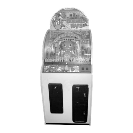
- Page 1 GODZILLA WARS Jnr. Operators Manual...
-
Page 2: Specifications
1. SPECIFICATIONS POWER SUPPLY :- 220/240 Volts AC CAPSULE SIZE :- 50mm DIAMETER C2000 TICKET DISPENSER DIMENSIONS :- 645(w) x 745(d) x 1665(h) (with header) WEIGHT:- 77kg. ACCESSORIES:- Keys: (Cash Door) ............ 2 (Coin Door) ............ 2 (Back Door) ............ 2 (Hopper Door) or (Dispenser Door) .... -
Page 3: Installation
2. PRECAUTIONS 2-1 Cautions When Installing. This game is designed for indoor use only. The game must not be installed outdoors or under the following conditions:- In areas directly exposed to sunlight, high humidity, direct water contact, dust, high heat or extreme cold. In locations that would present an obstacle in the case of an emergency, i.e. -
Page 4: How To Play
4. HOW TO PLAY Insert coin/s to establish credit, shown on the credit display, then press the dispense button once. Godzilla will begin to move and the background sounds will begin. Pressing the bomb pushbutton when lit will fire a ping-pong ball at Godzilla. If the timing is right the ball will go into Godzilla's mouth. - Page 5 Hopper Fuse (750ma) Hopper Switch Service switch Volume Control Test Switch Service LEDs Coin Counter Dispense Counter Service Bracket 5-2. Volume Control The volume control is fitted to the service bracket located inside the coin door. 5-3. Service Switch Pressing the service switch establishes a game credit without operating the coin counter.
- Page 6 Test 3 Ball Shooting Test The mouth opens and balls are automatically shot. The height to which balls are shot can be adjusted during this test. (see 5-6 below) Test 4 Sound Test All the game sounds are produced one after another. Test 5 Lamp and LED test The count lamps light one after another.
-
Page 7: Troubleshooting
6. TROUBLESHOOTING The game constantly monitors certain functions and if there is a failure certain LEDs or count lamps light as an indication. The following table indicates these conditions. Service LED Indication Fault Indicated Credit dispense pulse remains on Service switch remains on Mouth micro switch remains on Hopper test switch remains on Hopper microswitch remains on... - Page 8 7. PARTS 14,15 (behind header) Page...
- Page 9 Item Description Part No Building Vac-Form 88300850 Island Vac-Form 88300851 Field Guard Vac-Form 88300852 Rear Guard Acrylic 88300848 Play Panel ------------ Credit Display Panel 88300870 Side Acrylic L&R 88300846 Main Dome 88300845 Dome Stay LH 88300865 Dome Stay RH 88300866 Playfield Acrylic 88300847 Credit Display...
- Page 10 3, 22 4 (x2) 21, 23 10, 11 10, 11 18, 19, 20 Page...
- Page 11 Item Description Part No Opto Interrupter 88300893 Opto Interrupt Plate 88300901 Link Arm Stand-Off - Lower 88300896 Washer Link Arm Stand-Off 88300899 Mouth Motor 12v DC 40rpm 88300892 Crank Arm 88300900 Mouth Link Arm 88300894 Main Shaft & Mntg Assy 88300871 External Circlip 12mm 88300875...
- Page 12 Item Description Part No Flip Arm 88300903 Spacer 88300917 Rod - Short 88300907 Rod - Long 88300906 Spring 88300909 Solenoid 88300908 Ball Shooter Main Bracket 88300902 Solenoid Link Plate 88300904 Page...
- Page 13 8. SCHEMATIC - Power supply Page...
- Page 14 BOMB BUTTON SCHAFFNER MAINS ASSY POWER SUPPLY GND 3 BOARD SOL 3 EARTH 220-240V 21.5VAC MAINS 220VAC GND 3 11.6VAC 240VAC PCB ASSY EARTH 7.4VAC GND 1 ORANGE +24V DC24V AC24V1 SERVICE LED's BLACK GND 2 BGND BGND AC24V2 OVAC YELLOW J2-40P +12V...
Need help?
Do you have a question about the GODZILLA WARS Jnr. and is the answer not in the manual?
Questions and answers