Table of Contents
Advertisement
Available languages
Available languages
Quick Links
Advertisement
Chapters
Table of Contents

Related Manuals for ProLights PIXROLL6


Summary of Contents for ProLights PIXROLL6
- Page 1 PIXROLL6 LINEAR MOTORIZED PROJECTOR MANUALE UTENTE USER MANUAL IT - EN...
- Page 2 Music & Lights S.r.l. si riserva ogni diritto di elaborazione in qualsiasi forma delle presenti istruzioni per l’uso. La riproduzione - anche parziale - per propri scopi commerciali è vietata. Al fine di migliorare la qualità dei prodotti, la Music&Lights S.r.l. si riserva la facoltà di modificare, in qualunque momento e senza preavviso, le specifiche menzionate nel presente manuale di istruzioni.
-
Page 3: Table Of Contents
3. 20 Altre funzioni 4 Manutenzione 4. 1 Manutenzione e pulizia del sistema ottico 4. 2 Sostituzione fusibile 4. 3 Risoluzione dei problemi Certificato di garanzia Contenuto dell'imballo: • PIXROLL6 • Staffa di fissaggio • Cavo di alimenatazione • Manuale utente... -
Page 4: Sicurezza
PIXROLL6 ATTENZIONE! Prima di effettuare qualsiasi operazione con l’unità, leggere con attenzione questo manuale e conservarlo accuratamente per riferimenti futuri. Contiene informazioni importanti riguardo l’installazione, l’uso e la manutenzione dell’unità. SICUREZZA Avvertenze generali • I prodotti a cui questo manuale si riferisce sono conformi alle Direttive della Comunità Europea e per- tanto recano la sigla . -
Page 5: Informazioni Generali
PIXROLL6 INFORMAZIONI GENERALI Spedizioni e reclami Le merci sono vendute “franco nostra sede” e viaggiano sempre a rischio e pericolo del distributore/clien- te. Eventuali avarie e danni dovranno essere contestati al vettore. Ogni reclamo per imballi manomessi dovrà essere inoltrato entro 8 giorni dal ricevimento della merce. -
Page 6: Introduzione
Numerosi effetti dinamici pre-programmati sono disponibili nella memoria interna di PIXROLL6 e possono essere riprodot- ti in diverse modalità e macro colori. PIXROLL6 è un proiettore ideale per l’illuminazione di scenografie, effetti pixel mapping dinamici e blinders. -
Page 7: Elementi Di Comando E Di Collegamento
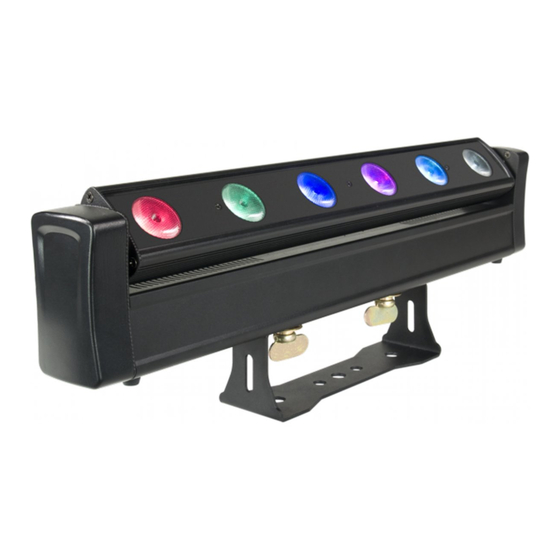
PIXROLL6 1.3 ELEMENTI DI COMANDO E DI COLLEGAMENTO MENU ENTER DOWN Pannello principale Fig.1 1. BARRA LED 6. POWER IN (connettore di potenza Neutrik) 2. STAFFA DI MONTAGGIO per il collegamento ad una presa di rete 3. PANNELLO DI CONTROLLO con display e 4... -
Page 8: Installazione
- 2 - INSTALLAZIONE 2.1 MONTAGGIO Il PIXROLL6 può essere collocato su un piano solido. Inoltre, grazie alle possibilità di fissaggio staffa (fig.2), l’unità può essere montata anche a testa in giù, su una traversa. Per il fissaggio occorrono dei supporti robusti per il montaggio. -
Page 9: Funzioni E Impostazioni
- 3 - FUNZIONI E IMPOSTAZIONI 3.1 FUNZIONAMENTO Per accendere il PIXROLL6, inserire la spina del cavo di alimentazione in una presa di rete (240V~ 50Hz). L’unità può essere comandata da un unità DMX di comando luce oppure svolgere autonomamente il suo programma. -
Page 10: Struttura Menu
PIXROLL6 3.3 STRUTTURA MENU MENU (LEVEL 1) (LEVEL 2) (LEVEL 3) (LEVEL 4) Auto Show Auto Show Mode Speed T Speed < Auto 0 > < Auto 0 > < 001 - 100 > < 001 - 100 > < Auto 1 >... - Page 11 PIXROLL6 Mode Dim Mode < DIM 1 > < Off > < DIM 1 > < DIM 2 > < DIM 3 > Back Lite Back Lite < On > < On > < 10 s > < 20 s >...
-
Page 12: Modalità Automatica
PIXROLL6 FUNZIONAMENTO STANDALONE Il PIXROLL6 dispone di diverse opzioni per il funzionamento senza un controller DMX: 3.4 MODALITÀ AUTOMATICA Per entrare nella modalità automatica e permettere all’unità di svolgere il suo programma Show autono- mamente: • Rimuovere qualsiasi controller DMX collegato all’unità. -
Page 13: Modalità Master/Slave
• Sull’unita Master selezionare il programma desiderato come indicato al paragrafo 3.4. • Servirsi dei connettori DMX del PIXROLL6 e di un cavo XLR per formare una catena di unità. In certe condizioni e lunghezze si consiglia di effettuare una terminazione come mostrato a pagina 15. -
Page 14: Collegamenti Della Linea Dmx
PIXROLL6 DMX Address: 33 DMX Address: 59 DMX Address: 85 DMX Address: 111 ... . DMX512 Controller Esempio di configurazione a 26 canali DMX Fig.4 3.13 COLLEGAMENTI DELLA LINEA DMX La connessione DMX è... -
Page 15: Costruzione Del Terminatore Dmx
PIXROLL6 3.14 COSTRUZIONE DEL TERMINATORE DMX La terminazione evita la probabilità che il segnale DMX 512, una volta raggiunta la fine della linea stessa venga riflesso indietro lungo il cavo, provocando, in certe condizioni e lunghezze, la sua sovrapposizione al segnale originale e la sua cancellazione. -
Page 16: Tabella Canali Dmx
PIXROLL6 3.15 TABELLA CANALI DMX MODE MODE FUNCTION FUNCTION Value Value 6 Ch 10 Ch 0% - 100% 000 - 255 0 - 100% 000 - 255 GREEN GREEN 0 - 100% 000 - 255 0 - 100% 000 - 255... - Page 17 PIXROLL6 MODE MODE FUNCTION FUNCTION Value Value 26 Ch 26 Ch RED 1 WHITE 5 0 - 100% 000 - 255 0 - 100% 000 - 255 GREEN 1 RED 6 0 - 100% 000 - 255 0% - 100%...
- Page 18 PIXROLL6 MODE MODE FUNCTION FUNCTION Value Value 30 Ch 30 Ch Chase8 151 - 170 GREEN 3 Chase9 171 - 190 0 - 100% 000 - 255 Chase10 191 - 210 BLUE 3 Chase11 211 - 230 0 - 100%...
-
Page 19: Informazioni Proiettore
PIXROLL6 3.16 INFORMAZIONI SUL PROIETTORE Auto Test Permette di verificare il corretto funzionamento dell’unità: • Dal menu iniziale premere il tasto MENU fino a quando sul display non appare [Info], quindi premere il tasto ENTER per confermare. • Attraverso i tasti UP/DOWN selezionare [Auto test], quindi premere il tasto ENTER per dare l’avvio al test automatico. -
Page 20: Altre Funzioni
PIXROLL6 3.20 ALTRE FUNZIONI Per il PIXROLL6 è possibile accedere alle seguenti funzioni: Offset • Per eseguire la calibrazione del movimento tilt, premere il tasto MENU fino a quando sul display non appare [Tilt Offeset] quindi premere il tasto ENTER per confermare. -
Page 21: Manutenzione
PIXROLL6 - 4 - MANUTENZIONE 4.1 MANUTENZIONE E PULIZIA DEL SISTEMA OTTICO • Durante gli interventi, assicurarsi che l’area sotto il luogo di installazione sia libera da personale non qualificato. • Spegnere l’unità, scollegare il cavo di alimentazione ed aspettare finché l’unità non si sia raffreddata. - Page 22 All rights reserved by Music & Lights S.r.l. No part of this instruction manual may be reproduced in any form or by any means for any commercial use. In order to improve the quality of products, Music&Lights S.r.l. reserves the right to modify the characteristics stated in this instruction manual at any time and without prior notice.
- Page 23 3. 18 Dimmer 3. 19 White balance 3. 20 Others functions 4 Maintenance 4. 1 Maintenance and cleaning the unit 4. 2 Fuse replacement 4. 3 Troubleshooting Warranty Packing content • PIXROLL6 • Mount bracket • Power cable • User manual...
-
Page 24: General Instructions
PIXROLL6 WARNING! Before carrying out any operations with the unit, carefully read this instruction manual and keep it with cure for future reference. It contains important information about the installation, usage and maintenance of the unit. SAFETY General instruction • The products referred to in this manual conform to the European Community Directives and are there- fore marked with . -
Page 25: General Information
PIXROLL6 GENERAL INFORMATION Shipments and claims The goods are sold “ex works” and always travel at the risk and danger of the distributor. Eventual dam- age will have to be claimed to the freight forwarder. Any claim for broken packs will have to be forwarded within 8 days from the reception of the goods. -
Page 26: Introduction
Numerous pre-programmed dynamic effects are available in the internal memory, which can be com- bined with multiple reproduction methods and colour macros. The PIXROLL6 is the ideal tool for the crea- tion of virtual lighting décors or for showing off actual architectural constructions on stage. -
Page 27: Operating Elements And Connections
PIXROLL6 1.3 OPERATING ELEMENTS AND CONNECTIONS MENU ENTER DOWN Main panel Fig.1 1. LED BAR 6. POWER IN (Neutrik connector) for connection 2. MOUNTING BRACKET to a socket (100-240V~/50-60Hz) via the 3. CONTROL PANEL with display and 4 button supplied mains cable used to access the control panel functions 7. -
Page 28: Installation
2.1 MOUNTING PIXROLL6 may be set up on a solid and even surface. The unit can also be mounted upside down to a cross arm. For fixing, stable mounting clips are required. The mounting place must be of sufficient stability and be able to support a weight of 10 times of the unit’s weight. -
Page 29: Functions And Settings
PIXROLL6 - 3 - FUNCTIONS AND SETTINGS 3.1 OPERATION Connect the supplied main cable to a socket (100-240 VAC-50/60 Hz). Then the unit is ready for operation and can be operated via a DMX controller or it independently performs its show program in succession. -
Page 30: Menu Structure
PIXROLL6 3.3 MENU STRUCTURE MENU (LEVEL 1) (LEVEL 2) (LEVEL 3) (LEVEL 4) Auto Show Auto Show Mode Speed T Speed < Auto 0 > < Auto 0 > < 001 - 100 > < 001 - 100 > < Auto 1 >... - Page 31 PIXROLL6 Mode Dim Mode < DIM 1 > < Off > < DIM 1 > < DIM 2 > < DIM 3 > Back Lite Back Lite < On > < On > < 10 s > < 20 s >...
-
Page 32: Automatic
PIXROLL6 STANDALONE This fixture has several options for operating without a DMX controller. Access these options via the con- trol panel on the back of the fixture. 3.4 AUTOMATIC This fixture has preprogrammed chases that may be triggered without a controller. Access these chases via the control panel on the back of the fixture. -
Page 33: Master/Slave Mode
3.12 DMX ADDRESSING To able to operate the PIXROLL6 with a light controller, adjust the DMX start address for the first a DMX channel. If e. g. address 33 on the controller is provided for controlling the function of the first DMX channel, adjust the start address 33 on the PIXROLL6. -
Page 34: Connection Of The Dmx Line
PIXROLL6 DMX Address: 33 DMX Address: 59 DMX Address: 85 DMX Address: 111 ... . DMX512 Controller Example 26 DMX channels configuration (26 Ch mode) Fig.4 3.13 CONNECTION OF THE DMX LINE DMX connection employs standard XLR connectors. -
Page 35: Construction Of The Dmx Termination
PIXROLL6 3.14 CONSTRUCTION OF THE DMX TERMINATION The termination avoids the risk of DMX 512 signals being reflected back along the cable when they reach- es the end of the line: under certain conditions and with certain cable lengths, this could cause them to cancel the original signals. -
Page 36: Dmx Control
PIXROLL6 3.15 DMX CONTROL MODE MODE FUNCTION FUNCTION Value Value 6 Ch 10 Ch 0% - 100% 000 - 255 0 - 100% 000 - 255 GREEN GREEN 0 - 100% 000 - 255 0 - 100% 000 - 255... - Page 37 PIXROLL6 MODE MODE FUNCTION FUNCTION Value Value 26 Ch 26 Ch RED 1 WHITE 5 0 - 100% 000 - 255 0 - 100% 000 - 255 GREEN 1 RED 6 0 - 100% 000 - 255 0% - 100%...
- Page 38 PIXROLL6 MODE MODE FUNCTION FUNCTION Value Value 30 Ch 30 Ch Chase8 151 - 170 GREEN 3 Chase9 171 - 190 0 - 100% 000 - 255 Chase10 191 - 210 BLUE 3 Chase11 211 - 230 0 - 100%...
-
Page 39: Fixture Information
PIXROLL6 3.16 FIXTURE INFORMATION Auto Test Allows you to check the proper functioning of the unit: • Press the button MENU so many times until the display show [Info] • Select [Auto Test], through the button UP/DOWN. • Press ENTER button to confirm; a test programme will be executed. -
Page 40: Others Functions
PIXROLL6 3.20 OTHERS FUNCTIONS It is possible to change the parameter value in the following way: Offset To set the corrective values (offset mode) for the tilt: • Press the button MENU so many times until shows [Tilt Offset], and press the button ENTER to confirm. -
Page 41: Maintenance
PIXROLL6 - 4 - MAINTENANCE 4.1 MAINTENANCE AND CLEANING THE UNIT • Make sure the area below the installation place is free from unwanted persons during setup. • Switch off the unit, unplug the main cable and wait until the unit has cooled down. - Page 43 Place Stamp Here Affrancare Spett.le Music&Lights S.r.l. Via Appia Km 136.200 04020 Itri (LT) Italy "...
- Page 48 MUSIC & LIGHTS S.r.l. Via Appia, km 136,200 - 04020 Itri (LT) - ITALY Phone +39 0771 72190 - Fax +39 0771 721955 www.musiclights.it - email: info@musiclights.it ISO 9001:2008 Certified Company...
Need help?
Do you have a question about the PIXROLL6 and is the answer not in the manual?
Questions and answers