
Related Manuals for Keysight 1143A


Summary of Contents for Keysight 1143A
- Page 1 User and Service Guide Publication number 01143-97000 First edition, June 2000 1143A Probe Offset Control and Power Module...
- Page 2 1143A Probe Offset Control and Power Module The 1143A Probe Offset Control and Power Module is an alternate control and power source for active probes. When an active probe cannot be powered from a connector at the front of the oscilloscope, the module is used to provide power, local offset control, and a remote offset interface.
- Page 3 Service Strategy The service strategy for the 1143A Probe Offset Control and Power Module is for field repair to the component level. See chapter 2, "Service," for further information.
- Page 4 In This Book This book provides use and service documentation for the 1143A Probe Offset Control and Power Module. It is divided into two chapters. Chapter 1 shows you how to set up and operate the instrument, both locally and remote.
-
Page 5: Table Of Contents
Contents 1 Operating the Power Module To inspect the power module 9 To check power requirements 11 To set the line voltage selection 11 To set up the power module 12 To use local offset 13 Remote Offset Input 14 2 Service General Information 20 Performance Characteristics 20... - Page 6 Contents Troubleshooting and Repair 32 To troubleshoot the power supplies 32 To troubleshoot the offset circuitry 33 To disassemble the instrument 34 Replaceable Parts 35 Theory of Operation 44 Schematic Diagrams 47 Index...
-
Page 7: Operating The Power Module
To inspect the power module 9 To check power requirements 11 To set the line voltage selection 11 To set up the power module 12 To use local offset 13 Remote Offset Input 14 Operating the Power Module... -
Page 9: To Inspect The Power Module
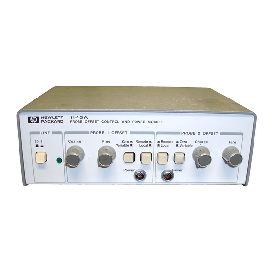
Introduction This chapter shows you how to connect and operate the 1143A Probe Offset Control and Power Module. The following information is covered in this chapter: • Initial Inspection • Power Requirements • Line Voltage Selection • Setting up the supply •... - Page 10 Operating the Power Module To inspect the power module Figure 1 1143A Probe Offset Control and Power Module Front Panel Figure 2 1143A Probe Offset Control and Power Module Rear Panel...
-
Page 11: To Check Power Requirements
Operating the Power Module To check power requirements To check power requirements The power module requires a power source of either 90 to 132/198 to 264 Vac, 47 to 440 Hz, 40 VA maximum. BEFORE CONNECTING POWER TO THIS INSTRUMENT, be sure the line C A U T I O N voltage switch on the rear panel of the instrument is set properly. -
Page 12: To Set Up The Power Module
Operating the Power Module To set up the power module To set up the power module The following paragraphs cover system preparation using the 1143A Probe Offset Control and Power Module. Set the line voltage selection. Use the power cable to connect the power module to the ac mains. -
Page 13: To Use Local Offset
Operating the Power Module To use local offset To use local offset This section defines the operating functions of the 1143A Probe Offset Control and Power Module. Set the controls that correspond to the Power connector being used. Turn on the power for the module. -
Page 14: Remote Offset Input
Operating the Power Module Remote Offset Input Remote Offset Input For automatic test applications, the offset provided by the 1143A Probe Offset Control and Power Module can be remotely controlled through a connector on the rear panel of the module. - Page 15 Operating the Power Module Remote Offset Input provides a positive offset in the probe. The output of the probe goes negative. • The offset voltage must be referenced to the appropriate (Probe 1 or Probe 2) offset common of the remote input connector. •...
-
Page 17: Service
General Information 20 Performance Characteristics 20 Operating Characteristics 20 General Characteristics 21 Recommended Test Equipment 23 Service Strategy 23 To clean the instrument 23 To return the instrument to Agilent Technologies for service 24 Testing Performance 25 Test Interval 25 Equipment Required 25 To test output voltages 26 Making Adjustments 27... - Page 19 Introduction This chapter provides service information for the 1143A Probe Offset Control and Power Module. The following topics are included in this chapter: • Specifications and Characteristics • Recommended Test Equipment • Repair Strategy • Returning to Agilent Technologies for Service •...
-
Page 20: General Information
General Information This section covers general information to be used for servicing the 1143A Probe Offset Control and Power Module. Performance Characteristics The following are the performance characteristics for the 1143A. These characteristics are nominal and non-warranted. Table 2 Performance Characteristics +17.3 Vdc ±500 mV... -
Page 21: General Characteristics
Service General Information General Characteristics The following general characteristics apply to the 1143A. Table 4 General Characteristics Environmental Conditions Operating Non-operating 0 °C to +55 °C (32 °F to +131 °F) −40 °C to +70 °C (−40 °F to +158 °F) Temperature up to 90% relative humidity at +65 °C... - Page 22 Service General Information Product Regulations IEC 348 Safety UL 1244 CSA-C22.2 No.231 (Series M-89) This product meets the requirement of the European Communities (EC) EMC Directive 89/336/EEC. EN55011/CISPR 11 (ISM, Group 1, Class A equipment) Emissions SABS RAA Act No. 24 (1990) EN50082-1 Code Notes...
-
Page 23: Recommended Test Equipment
P = Performance Tests, A = Adjustments, T = Troubleshooting Service Strategy The 1143A Probe Offset Control and Power Module consists of simple power supplies and op-amp variable current sources. Circuitry is simple and components are available off the shelf, so the service strategy is component-level repair. -
Page 24: To Return The Instrument To Hp For Service
Service General Information To return the instrument to Agilent Technologies for service Before shipping the instrument to Agilent Technologies, contact your nearest Agilent Technologiessales office for additional details. Write the following information on a tag and attach it to the instrument. -
Page 25: Testing Performance
Testing Performance The procedure in this section checks the probe power output voltage using the value given in "Performance Characteristics" in this chapter as a standard. Test Interval This procedure may be performed for incoming inspection of the instrument and should be performed periodically thereafter to ensure and maintain peak performance. -
Page 26: To Test Output Voltages
Service Testing Performance To test output voltages This test checks the output voltages of the supply. The voltage requirement is not a specification, but is checked to assure proper operation of the probes. Requirement: +17.3 Vdc ±500 mV and −17.3 Vdc ±500 mV Equipment Required Equipment Critical Specification... -
Page 27: Making Adjustments
Making Adjustments This section provides adjustment procedures for the 1143A Probe Offset Control and Power Module. Safety Read the Safety Summary at the front of this manual before servicing the instrument. Before performing any procedure, review it for cautions and warnings. - Page 28 Figure 5 Ground TP5 Probe 1 Offset Negative Current Threshold R61 Positive Current Threshold R60 +17.3 V TP1 Positive Voltage Adjust R38 Probe 1 Offset Probe 1 Offset –17.3 V TP2 Probe 2 Offset Zero R9 Zero R27 1143A Adjustment Locations...
-
Page 29: To Prepare The Equipment
Service Making Adjustments To prepare the equipment Turn off the front-panel power switch and remove the power cord. When power is applied there are hazardous voltages inside the instrument. W A R N I N G Observe reasonable safety precautions in order to avoid injury or death. Disconnect any probes from the front panel. -
Page 30: To Adjust Power Supply Current Limits
Service Making Adjustments To adjust power supply current limits This procedure sets the current limit of the supplies to approximately 330 mA for each supply. Equipment Required Equipment Critical Specification Recommended Model/Part Digital Multimeter Better than 0.1% accuracy 3458A 50 Ω, 10 W, 1% Resistor 0811-3707 Use the adjustment locator on page 28 to find the test points and adjustments. -
Page 31: To Adjust Offset Zero
Service Making Adjustments To adjust offset zero This procedure adjusts the probe offset drive current to zero when the offset is turned off. Equipment Required Equipment Critical Specification Recommended Model/Part Digital Multimeter Better than 0.1% accuracy 3458A 511 Ω, 0.5 W, 1% Resistor 0757-0814 Use the adjustment locator on page 28 to find the test points and adjustments. -
Page 32: Troubleshooting And Repair
Troubleshooting and Repair This section provides troubleshooting and repair techniques and information. Read the Safety Summary at the front of this manual before servicing the instrument. Before performing any procedure, review it for cautions and warnings. When power is applied there are dangerous voltages present in this W A R N I N G equipment. -
Page 33: To Troubleshoot The Offset Circuitry
Service Troubleshooting and Repair The −17.3 supply is out of tolerance • Make sure the +17.3 V supply is in tolerance. • Make sure the supply is not loaded into current limit. • Check the values of parts in the voltage divider sticks that feed the error amplifier of the −17.3 V regulator (R47–R51). -
Page 34: To Disassemble The Instrument
Service Troubleshooting and Repair To disassemble the instrument Use the following procedure to disassemble the 1143A Probe Offset Control and Power Module. Hazardous voltages exist on the power module. Failure to adhere closely to W A R N I N G the following procedures can cause electrical shock. -
Page 35: Replaceable Parts
Replaceable Parts This section contains information for ordering parts. Service support for the 1143A Probe Offset Control and Power Module is to the component level. Parts Lists Table 6, page 37, is an instrument-level parts list. Table 7, page 38, is a parts list for the PC assembly (A1) in the power module. - Page 36 Service Troubleshooting and Repair Direct Mail Order System Within the USA, Agilent Technologies can supply parts through a direct mail order system. There are several advantages to this system: • Direct ordering and shipment from the Agilent Technologiesparts center in California, USA. •...
- Page 37 Service Troubleshooting and Repair Table 6 1143A Replaceable Parts Ref. Part Mfr. Mfr. Part Des. Number Description Code Number 01143-66501 PC ASSEMBLY-POWER AND CONTROL 28480 01143-66501 0515-0374 SCREW-MACHINE M3 10MM-LG (PC board mounting) 00000 ORDER BY DESCR. 0515-1031 SCREW-MACH M3 6MM-LG 90-DEG-FLH-HD (cover 00000 ORDER BY DESCR.
- Page 38 Service Troubleshooting and Repair Table 7 Power and Control Assembly Replaceable Parts Ref. Part Mfr. Mfr. Part Des. Number Description Code Number Prefix the reference designators with A1 CAPACITOR-FXD 0.022UF ±10% 63VDC 0160-5578 28480 0160-5578 CAPACITOR-FXD 0.022UF ±10% 63VDC 0160-5578 28480 0160-5578 0180-3298...
- Page 39 Service Troubleshooting and Repair Table 7 (cont.) Power and Control Assembly Replaceable Parts Ref. Part Mfr. Mfr. Part Des. Number Description Code Number 0515-1579 SCREW-MACHINE ASSEMBLY M5 X 0.8 18MM-LG 28480 0515-1579 01142-21101 HEAT SINK 28480 01142-21101 1251-4743 CONNECTOR-AC PWR MALE 28480 1251-4743 1252-1487...
- Page 40 Service Troubleshooting and Repair Table 7 (cont.) Power and Control Assembly Replaceable Parts Ref. Part Mfr. Mfr. Part Des. Number Description Code Number 0698-6362 RESISTOR 1K 0.1% 0.125W TF TC=0±25 28480 0698-6362 0698-6624 28480 0698-6624 RESISTOR 2K 0.1% 0.125W TF TC=0±25 0698-3161 RESISTOR 38.3K 1% 0.125W TF TC=0±100 24546...
- Page 41 Service Troubleshooting and Repair Table 7 (cont.) Power and Control Assembly Replaceable Parts Ref. Part Mfr. Mfr. Part Des. Number Description Code Number 0699-2403 28480 0699-2403 RESISTOR 0.33 5% 0.7W MO TC=0±200 0698-4413 RESISTOR 154 1% 0.125W TF TC=0±100 24546 CT4-1/8-T0-154R-F 0757-0453 RESISTOR 30.1K 1% 0.125W TF TC=0±100...
- Page 42 Service Troubleshooting and Repair Table 8 Manufacturers’ Code List Mfr. No. Name Address 00000 Any satisfactory supplier 04713 Notarial Semiconductor Products Phoenix, AZ 85008 06665 Precision Monolithic Inc Santa Clara, CA 95050 01295 Texas Inst. Inc Semicond Cmpnt Div Dallas, TX 75222 19701 Mepco/Electra Corp Mineral Wells, TX 76067...
- Page 43 Service Troubleshooting and Repair Figure 6 Power and Control Assembly Component Locator...
-
Page 44: Theory Of Operation
Troubleshooting and Repair Theory of Operation The 1143A Probe Offset Control and Power Module provides power and offset control for two active probes, such as the 54701A. Use the schematics at the end of this chapter to illustrate the following discussion. The schematics cover the power and control assembly A1. - Page 45 Service Troubleshooting and Repair Positive Supply Refer to schematic 1. The reference for the positive supply is the +1.5 V reference from the IC, fed to the noninverting input of the error amplifier. The output voltage is divided through the POSITIVE VOLTAGE ADJUST and fed to the inverting input of the error amplifier.
-
Page 47: Schematic Diagrams
Service Troubleshooting and Repair Schematic Diagrams Schematics are provided for the 1143A Probe Offset Control and Power Module which is component-level repairable. Schematics for the power and control assembly are sequentially numbered in the figure title at the bottom of the page. Schematic numbers are used to cross reference signal connections between the schematics. - Page 48 Service Troubleshooting and Repair Figure 8 Schematic 1. Line Input and Positive Supply...
- Page 49 Service Troubleshooting and Repair Figure 9 Schematic 2. Negative Supply...
- Page 50 Service Troubleshooting and Repair Figure 10 Schematic 3. Probe 1 Offset Control IC Connections Not Shown (schematics 3 & 4) Connection IC Group +17.3 V U1, U4 –17.3 V +17.3 V U2, U5 –17.3 V 1, 5, 8...
- Page 51 Service Troubleshooting and Repair Figure 11 Schematic 4. Probe 2 Offset Control Figure 12 Probe Power Cable Diagram (W2)
-
Page 53: Index
Index accessories available, 2 offset safety, 27 accessories supplied, 2 adjusting, 31 schematic diagrams, 47–51 adjusting, 27–31 local, 13 service strategy, 3, 23 current limits, 30 remote, 14–15, 17 set up, 12 offset zero, 31 troubleshooting, 33 storage environment, 21 preparing equipment, 29 variable, 13 switch... - Page 54 1900 Garden of the Gods Road Colorado Springs, CO 80907 USA declares, that the product Product Name: Oscilloscope Probe/Power Supply Model Number(s): 54701A/1143A Product Option(s): conforms to the following Product Specifications: Safety: IEC 348:1978 / HD 401 S1:1981 UL 1244 CSA-C22.2 No.
- Page 55 • © Copyright Agilent Safety Safety Symbols Service instructions are for Technologies 2000 trained service personnel. To This apparatus has been avoid dangerous electric designed and tested in All Rights Reserved. shock, do not perform any accordance with IEC Instruction manual symbol: service unless qualified to do Publication 348, Safety the product is marked with...
- Page 56 This Agilent Technologies This is the first edition of the Agilent Technologies edition and of any changed product has a warranty 1143A Probe Offset Control specifically disclaims the pages to that edition. against defects in material and Power Module User...
Need help?
Do you have a question about the 1143A and is the answer not in the manual?
Questions and answers