Table of Contents
Advertisement
Quick Links
A l l t e s t I n s t r u me n t s , I n c .
5 0 0 C e n t r a l A v e .
F a r mi n g d a l e , N J 0 7 7 2 7
P : ( 7 3 2 ) 9 1 9 - 3 3 3 9
F : ( 7 3 2 ) 9 1 9 - 3 3 3 2
a l l t e s t . n e t
s s a l e s @ a l l t e s t . n e t
T h e t e s t & me a s u r e me n t
e q u i p me n t y o u n e e d a t
t h e p r i c e y o u w a n t .
A l l t e s t c a r r i e s t h e w o r l d ' s l a r g e s t s e l e c t i o n o f
u s e d / r e f u r b i s h e d b e n c h t o p t e s t & me a s u r e me n t
e q u i p me n t a t 5 0 % t h e p r i c e o f n e w .
O O u r e q u i p me n t i s g u a r a n t e e d w o r k i n g , w a r r a n t i e d , a n d
a v a i l a b l e w i t h c e r t i f i e d c a l i b r a t i o n f r o m o u r i n - h o u s e s t a f f
o f t e c h n i c i a n s a n d e n g i n e e r s .
• 1 0 + f u l l t i me t e c h n i c i a n s w i t h o v e r 1 5 0 y e a r s o f
s p e c i a l i z a t i o n
• 9 0 d a y w a r r a n t y & 5 d a y r i g h t o f r e t u r n o n a l l
e q u i p me n t
• • 1 - 3 y e a r w a r r a n t i e s f o r n e w a n d
p r e mi u m- r e f u r b i s h e d e q u i p me n t
• E v e r y u n i t t e s t e d t o O E M s p e c i f i c a t i o n s
• S a t i s f a c t i o n g u a r a n t e e d
Y o u h a v e p l a n s , w e w i l l h e l p y o u a c h i e v e t h e m.
A n y p r o j e c t . A n y b u d g e t .
t
G e t a q u o t e t o d a y !
C C a l l ( 7 3 2 ) 9 1 9 - 3 3 3 9 o r e ma i l s a l e s @a l l t e s t . n e t .
Advertisement
Table of Contents
Troubleshooting

Related Manuals for Keysight 1143A

Summary of Contents for Keysight 1143A
- Page 1 T h e t e s t & me a s u r e me n t e q u i p me n t y o u n e e d a t t h e p r i c e y o u w a n t . A l l t e s t I n s t r u me n t s , I n c .
- Page 2 Keysight 1143A Probe Offset Control and Power Module User’s Guide...
- Page 3 FAR and 1143A Probe Offset Control and Power Module User’s Guide...
-
Page 4: Table Of Contents
Disassembling The 1143A / 30 Troubleshooting The Power Supplies / 32 Troubleshooting The Offset Circuitry / 33 Replaceable Parts / 34 Theory of Operation / 48 Returning the Instrument For Service / 58 1143A Probe Offset Control and Power Module User’s Guide... - Page 5 Contents 1143A Probe Offset Control and Power Module User’s Guide...
-
Page 6: Using The 1143A
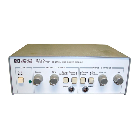
The 1143A Probe Offset Control and Power Module is an alternate control and power source for active probes. When an active probe cannot be powered from a connector at the front of the oscilloscope, the 1143A is used to provide power, local offset control, and a remote offset interface. - Page 7 Technologies office will arrange for repair or replacement at Keysight Technologies' option without waiting for claim settlement. Service Strategy The service strategy for the 1143A Probe Offset Control and Power Module is for field repair to the component level. Refer to Chapter 2, “Servicing the 1143A.
- Page 8 Use a soft cloth dampened with mild soap and water to clean the instrument. Care must be taken not to use a harsh soap which will damage the water-based paint finish of the instrument. 1143A Probe Offset Control and Power Module User’s Guide...
-
Page 9: Safety Information
Failure to comply with these precautions or with specific warnings or operating instructions in the product manuals violates safety standards of design, manufacture, and intended use of the instrument. Keysight Technologies assumes no liability for the customer's failure to comply with these requirements. - Page 10 If the instrument is damaged, or if it fails to operate according to the characteristics in WARNING this manual, remove the power cord and contact Keysight Technologies. Only fuses with the required rated current, voltage, and specified type (normal blow, WARNING time delay, etc.) should be used.
- Page 11 This unit is not constructed to be waterproof or dust proof, so do not use it in a very WARNING dusty environment or in one where it will get wet. For indoor use only. Do not use the instrument in a manner not specified by the manufacturer. WARNING 1143A Probe Offset Control and Power Module User’s Guide...
-
Page 12: Using The 1143A
Using the 1143A This section of the manual contains information and instructions for installation and use of the 1143A as an auxiliary power supply. Use of probe controls is covered in the guide for the probe. Checking the Power Requirements and Fuse The power module requires a power source of either 115 Vac or 230 Vac, 47 to 440 Hz, 40VA maximum. - Page 13 Use the power cable to connect the power module to the ac mains. Connect the probe power cable 1143A’s front-panel Power connector. Red dots on the cable connector housing and 1143A are aligned with the connector keys. Align the dots when inserting the cable connector into the power connector.
- Page 14 Turn on the 1143A power. Set the appropriate Remote/Local switch. • To control the probe offset voltage with the 1143A, set the switch to Local. • To control the probe offset voltage remotely, set the switch to Remote and refer “Remote Control"...
-
Page 15: Remote Control
Remote Control Remote Control For automatic test applications, the offset provided by the 1143A can be remotely controlled through the rear-panel a connector. This is a standard 9-pin, female, D-sub-miniature connector shown in Table 2. This style is the same as that used on some personal computer monitor cables, which provides an economical way to connect the remote input to the controller interface on an automatic test system. - Page 16 0.0V, disconnected, or grounded. To minimize dc offset errors and potential noise coupling caused by ground loops, electrically N OTE isolate all connections between the remote input connector and the controlling system. 1143A Probe Offset Control and Power Module User’s Guide...
-
Page 17: Characteristics
Characteristics Characteristics Table 3 lists the performance characteristics for the 1143A. These characteristics are nominal and non-warranted. Table 4 lists the operating characteristics. The remainder of this section provides general characteristics. Table 3 Performance Characteristics Item Specification Supply Output Voltage +17.3 Vdc ±500 mV... - Page 18 Item Specification Voltage 115/230 Vac, 47 to 440 Hz Power 40 VA maximum Table 7 Weight (General Characteristics) Item Specification approximately 1.5 kg (3.4 lb) Shipping approximately 2.4 kg (5.4 lb) 1143A Probe Offset Control and Power Module User’s Guide...
- Page 19 Characteristics Figure 3 1143A Dimensions Product Regulations Safety • CAN/CSA-C22.2 No. 61010-1-12 • ANSI/UL Standard 61010-1 • ANSI/ISA-61010-1 (82.02.01) 1143A Probe Offset Control and Power Module User’s Guide...
-
Page 20: Testing Performance
“Characteristics" on page 16 as a standard. This procedure may be performed for incoming inspection of the 1143A and should be performed periodically thereafter to ensure and maintain peak performance. The recommended test interval is yearly or every 2,000 hours of operation. Amount of use, environmental conditions, and the user's experience concerning need for testing will contribute to verification requirements. - Page 21 Testing Performance Figure 4 Probe Power Output Connector Connect the mains power to the 1143A and turn the front-panel power switch on. Measure the voltage between ground and pin 1 of the connector. It should be +17.3 Vdc, ±500 mV.
-
Page 22: Contacting Keysight
• Seal the shipping container securely. • Mark the shipping container as FRAGILE. In all correspondence, refer to the instrument by model number and full serial number. 1143A Probe Offset Control and Power Module User’s Guide... - Page 23 Contacting Keysight 1143A Probe Offset Control and Power Module User’s Guide...
-
Page 24: Servicing The 1143A
Figure 6 on page 30 shows the internal location of the protective earth terminal. The 1143A consists of simple power supplies and op-amp variable current sources. Circuitry is simple and components are available off the shelf, so the service strategy is component-level repair. The troubleshooting, parts lists, theory of operation, and schematics support this repair level. - Page 25 Equipment Required Critical Specifications Recommended Model/Part Accuracy: ±0.1% 3457A P,A,T Resistor 511Ω, 0.5W, 1% 0757-0814 Resistor 50Ω, 10W, 1% 0811-3707 a P = Performance Tests, A = Adjustments, T = Troubleshooting 1143A Probe Offset Control and Power Module User’s Guide...
-
Page 26: Making Adjustments
Adjustment Interval There is no recommended adjustment interval for the 1143A. These adjustments are considered factory adjustments and do not require periodic maintenance. Make adjustments only when directed by other service procedures. Defining an adjustment interval will depend on the user's experience. - Page 27 Disconnect any probes from the front panel. With a T10 Torx driver, remove 4 flathead screws and remove the top chassis. 1143A Probe Offset Control and Power Module User’s Guide...
- Page 28 Refer to Figure 5 on page 26 to find the test points and adjustments. Table 11 Equipment Required Equipment Critical Specification Recommended Model/Part Digital Multimeter Better than 0.1% accuracy 3458A 1143A Probe Offset Control and Power Module User’s Guide...
- Page 29 Connect the DVM between TP5 (ground) and TP3 (Probe 1 Offset). Connect the 511Ω resistor between TP5 and TP3. Adjust R9 (Probe 1 Offset Zero) for a reading of 0.0V ±100 µV. 1143A Probe Offset Control and Power Module User’s Guide...
- Page 30 Adjust R27 (Probe 2 Offset Zero) for a reading of 0.0V ±100 µV. If the offset zero cannot be adjusted into tolerance, refer to “The +17.3 Supply Won't Adjust Into Tolerance" on page 32. 1143A Probe Offset Control and Power Module User’s Guide...
-
Page 31: Disassembling The 1143A
Figure 6 Location of Protective Earth Terminal At the PC board, disconnect the cables that connect the front panel probe power outputs. Note the orientation of the knobs. Remove the four knobs. 1143A Probe Offset Control and Power Module User’s Guide... - Page 32 Remove the two heat sink spacers from the standoffs that were directly under the hearsing. Reverse the procedure to reassemble the power module. 1143A Probe Offset Control and Power Module User’s Guide...
-
Page 33: Troubleshooting The Power Supplies
There is a Current Limit Problem • Check that the supply is not loaded into current limit. • Check the values of parts in the current sense circuit, particularly the current sense resistors (R42 and R53). 1143A Probe Offset Control and Power Module User’s Guide... -
Page 34: Troubleshooting The Offset Circuitry
The offset output is a ±5 mA current. Into a 511Ω resistor the nominal voltage swing should be ±2.58 Vdc but it depends on the value of the resistor. For the most accurate test, measure the offset current swing directly. 1143A Probe Offset Control and Power Module User’s Guide... -
Page 35: Replaceable Parts
Replaceable Parts Replaceable Parts This section contains information for ordering parts. Service support for the 1143A Probe Offset Control and Power Module is to the component level. Parts Lists Table 14 on page 37, is an instrument-level parts list. Table 15 on page 38, is a parts list for the PC assembly (A1) in the power module. - Page 36 Ordering Information To order a part in the material list, quote the Keysight Technologies part number, indicate the quantity desired, and address the order to the nearest Keysight Technologies sales office. To order a part not listed in the material list, include the instrument part number, instrument serial number, a description of the part (including its function) and the number of parts required.
- Page 37 Replaceable Parts In order for Keysight Technologies to provide these advantages, please send a check or money order with each order. Mail order forms and specific ordering information are available through your local Keysight Technologies office. Addresses and telephone numbers are located in a separate document shipped with the manuals.
- Page 38 8120-0698 CABLE-POWER (Option 904-250V USA/CANADA) 28480 8120-0698 8120-2296 CABLE-POWER (Option 906-SWIT) 28480 8120-2296 8120-2957 CABLE-POWER (Option 912-DEN) 28480 8120-2957 8120-4600 CABLE-POWER (Option 917-AFRICA) 28480 8120-4600 8120-4754 CABLE-POWER (Option 918-JAPAN) 28480 8120-4754 1143A Probe Offset Control and Power Module User’s Guide...
- Page 39 CAPACITOR-FXD 0.01UF ±10% 100VDC CER 28480 0160-6500 0160-6500 CAPACITOR-FXD 0.01UF ±10% 100VDC CER 28480 0160-6500 0160-5471 CAPACITOR-FXD 0.1UF ±5% 50VDC MET-POLYE 28480 0160-5471 0160-5471 CAPACITOR-FXD 0.1UF ±5% 50VDC MET-POLYE 28480 0160-5471 C24-25 NOT ASSIGNED 1143A Probe Offset Control and Power Module User’s Guide...
- Page 40 1400-1604 SPACER-LED MOUNT 28480 1400-1604 TRANSFORMER SUPPORT 28480 01142-247 01142-2470 WASHER-TRANSFORMER SUPPORT 28480 01142-288 01142-2880 1205-0732 SPRING CLIP 28480 1205-0732 0361-0685 RIVET-BLIND DR-PIN RNDH 0.125DIA 28480 0361-0685 0340-1211 INSULATOR-THERMAL 28480 0340-1211 1143A Probe Offset Control and Power Module User’s Guide...
- Page 41 28480 2100-4250 2100-3659 RESISTOR-TRMR 20K 10% TKF TOP-ADJ 17-TRN 28480 2100-3659 0757-0199 RESISTOR 21.5K 1% 0.125W TF TC=0±100 24546 CT4-1/8-T0- 2152-F 0757-0280 RESISTOR 1K 1% 0.125W TF TC=0±100 24546 CT4-1/8-T0- 1001-F 1143A Probe Offset Control and Power Module User’s Guide...
- Page 42 2100-4250 RESISTOR-VARIABLE 10K 20% 28480 2100-4250 2100-4250 RESISTOR-VARIABLE 10K 20% 28480 2100-4250 2100-3659 RESISTOR-TRMR 20K 10% TKF TOP-ADJ 17-TRN 28480 2100-3659 0757-0199 RESISTOR 21.5K 1% 0.125W TF TC=0±100 24546 CT4-1/8-T0- 2152-F 1143A Probe Offset Control and Power Module User’s Guide...
- Page 43 24546 CT4-1/8-T0- 3012-F 0699-2403 RESISTOR 0.33 5% 0.7W MO TC=0±200 28480 0699-2403 0698-4413 RESISTOR 154 1% 0.125W TF TC=0±100 24546 CT4-1/8-T0- 154R-F 0757-0818 RESISTOR 825 1% 0.5W TF TC=0±100 28480 0757-0818 1143A Probe Offset Control and Power Module User’s Guide...
- Page 44 24546 CT4-1/8-T0- 1001-F 0698-4413 RESISTOR 154 1% 0.125W TF TC=0±100 24546 CT4-1/8-T0- 154R-F 0757-1078 RESISTOR 1.47K 1% 0.5W TF TC=0±100 28480 0757-1078 2100-2497 RESISTOR-TRMR 2K 10% TKF TOP-ADJ 1-TRN 73138 82PR2K 1143A Probe Offset Control and Power Module User’s Guide...
- Page 45 1826-0774 IC V RGLTR-V-REF-FXD 1.22/1.24V TO-92 27014 LM385BZ-1. 1826-1992 IC OP AMP 06665 OP-200 1826-1049 IC OP AMP PRCN 8-DIP-C PKG 06665 OP-27GZ 1826-0774 IC V RGLTR-V-REF-FXD 1.22/1.24V TO-92 27014 LM385BZ-1. 1143A Probe Offset Control and Power Module User’s Guide...
- Page 46 28480 1902-0964 1902-0964 DIODE-ZNR 18V 5% DO-35 PD=0.4W TC=+.09% 28480 1902-0964 WIRE ASSEMBLY-SAFETY GROUND 28480 01141-616 01141-6160 Table 16 Component Locations for A1 Assembly Grid Grid Grid Grid Grid Grid Grid 1143A Probe Offset Control and Power Module User’s Guide...
- Page 47 Replaceable Parts Table 16 Component Locations for A1 Assembly Grid Grid Grid Grid Grid Grid Grid 1143A Probe Offset Control and Power Module User’s Guide...
- Page 48 Replaceable Parts Figure 7 A1 Assembly Component Locations 1143A Probe Offset Control and Power Module User’s Guide...
-
Page 49: Theory Of Operation
Symbols on schematics are based on current ANSI and IEEE standards. Table 17 Additional Schematic Symbols Symbol Description Tool-aided adjustment. Test point with measurement aid. Connection through machine screw. 1143A Probe Offset Control and Power Module User’s Guide... - Page 50 The output drives a pass transistor which drives the load with it's collector. A simplified diagram of the voltage regulator IC is shown in the figure below. 1143A Probe Offset Control and Power Module User’s Guide...
- Page 51 Fault Alert (not used) +1.5V Reference Fault Delay Current Threshold Adjust Driver Sink – Input Voltage Driver Source – Current Sense Compensation/Shutdown + Current Sense 0.V. Latch Out/Reset Non-Inverting Input Crowbar Gate 1143A Probe Offset Control and Power Module User’s Guide...
- Page 52 The voltage across current sense resistor R42 is fed to the current sense amplifier. The current is fold-back limited by R41 and VR1. The POSITIVE CURRENT THRESHOLD adjustment sets the current limit threshold in the amplifier. 1143A Probe Offset Control and Power Module User’s Guide...
- Page 53 The output of U1B drives current source U2. The output of U2 swings ±5 mA, depending on the offset control input. The offset control drives a 500Ω load in the 54701A active probe. 1143A Probe Offset Control and Power Module User’s Guide...
- Page 54 Theory of Operation Figure 9 Schematic 1. Line Input and Positive Supply 1143A Probe Offset Control and Power Module User’s Guide...
- Page 55 Theory of Operation Figure 10 Schematic 2. Negative Supply 1143A Probe Offset Control and Power Module User’s Guide...
- Page 56 Theory of Operation Figure 11 Schematic 3. Probe 1 Offset Control 1143A Probe Offset Control and Power Module User’s Guide...
- Page 57 Theory of Operation Table 19 IC Connections Not Shown (Schematics 3 & 4) Connection IC Group Connector +17.3V U1, U4 –17.3V +17.3V U2, U5 –17.3V 1, 5, 8 1143A Probe Offset Control and Power Module User’s Guide...
- Page 58 Theory of Operation Figure 12 Schematic 4. Probe 2 Offset Control Figure 13 Probe Power Cable Diagram (W2) 1143A Probe Offset Control and Power Module User’s Guide...
-
Page 59: Returning The Instrument For Service
Pack the instrument in foam or other shock absorbing material and place it in a strong shipping container. You can use the original shipping materials or order materials from an Keysight Technologies sales office. If neither are available, place 3 to 4 inches of shock-absorbing material around the instrument and place it in a box that does not allow movement during shipping. - Page 60 Grounding, repair, grounding, replaceable parts, humidity, safety information, Schematic 1, Schematic 2, Schematic 3, initial inspection, Schematic 4, instrument markings, schematic diagrams, Supply Current, Supply Output Voltage, knobs, 1143A Probe Offset Control and Power Module User’s Guide...
- Page 61 Index 1143A Probe Offset Control and Power Module User’s Guide...
- Page 63 This information is subject to change without notice. © Keysight Technologies, 2017 Printed in Malaysia Second Edition, May 2017 *01143-97003* 01143-97003 www.keysight.com...
Need help?
Do you have a question about the 1143A and is the answer not in the manual?
Questions and answers