Table of Contents
Advertisement
Advertisement
Table of Contents

Summary of Contents for Kalatec Automacao 2DM860H
- Page 1 DIGITAL STEPPER DRIVER MANUAL 2DM860H WWW.KALATEC.COM.BR...
- Page 2 Shenzhen Just Motion Control Electro-mechanics Co., Ltd 0755-26509689 Thanks for selecting JMC stepper motor driver. We hope that the superior performance, outstanding quality, excellent cost performance of our product can help you accomplish your motion control project. The content in this manual has been carefully prepared and is believed to be accurate, but no responsibility is assumed for inaccuracies.
-
Page 3: Table Of Contents
Shenzhen Just Motion Control Electro-mechanics Co., Ltd 0755-26509689 Contents 1. Overview.................... - 4 - 2. Features....................- 4 - 3. Ports Introduction................- 5 - 3.1 ALM signal output ports............- 5 - 3.2 Control Signal Input Ports............- 6 - 3.3 Power Interface Ports.............. - 7 - 4. -
Page 4: Overview
The control algorithm of smoothness can enhance the acceleration and deceleration of motor. Its unique features make the 2DM860H to be an ideal solution for applications. 2. Features Parameter auto-setup and motor self-test ... -
Page 5: Ports Introduction
Shenzhen Just Motion Control Electro-mechanics Co., Ltd 0755-26509689 Support PUL/DIR and CW/CCW modes Storage the position of motor Optically isolated input and compatible with 5V or 24V User-defined micro steps Microstep resolutions and Output current programmable ... -
Page 6: Control Signal Input Ports
Shenzhen Just Motion Control Electro-mechanics Co., Ltd 0755-26509689 3.2 Control Signal Input Ports Port Symbol Name Remark DIR- Direction signal- Compatible with 5V or 24V DIR+ Direction signal+ PLS- Pulse signal - Compatible with 5V or 24V PLS+ Pulse signal + ENA- Enable signal - Compatible with... -
Page 7: Power Interface Ports
Shenzhen Just Motion Control Electro-mechanics Co., Ltd 0755-26509689 3.3 Power Interface Ports Port Identification Symbol Name Remark Phase A+ Motor Phase A Motor Phase Phase A- Wire Input Ports Phase B+ Motor Phase B Phase B- Input Power + Power Input AC24V-80V Ports DC30V-110V... -
Page 8: Technological Index
Shenzhen Just Motion Control Electro-mechanics Co., Ltd 0755-26509689 4. Technological Index Input Voltage 24~80VAC 30~110VDC Output Current 7.5A Pulse Frequency max 200K Communication rate 57.6Kbps Over current peak value 12A±10% Protection Over voltage value 130V The over position error range can be set through the HISU Overall Dimensions(mm)... -
Page 9: Connections To Control Signal
Shenzhen Just Motion Control Electro-mechanics Co., Ltd 0755-26509689 5. Connections to Control Signal 5.1 Connections to Common Anode Remark: VCC is compatible with 5V or 24V; R(3~5K) must be connected to control signal terminal. - 9 -... -
Page 10: Connections To Common Cathode
Shenzhen Just Motion Control Electro-mechanics Co., Ltd 0755-26509689 5.2 Connections to Common Cathode Remark: VCC is compatible with 5V or 24V; R(3~5K) must be connected to control signal terminal. - 10 -... -
Page 11: Connections To Differential Signal
Shenzhen Just Motion Control Electro-mechanics Co., Ltd 0755-26509689 5.3 Connections to Differential Signal Remark: VCC is compatible with 5V or 24V; R(3~5K) must be connected to control signal terminal. - 11 -... -
Page 12: Connections To 232 Serial Communication Interface
Shenzhen Just Motion Control Electro-mechanics Co., Ltd 0755-26509689 5.4 Connections to 232 Serial Communication Interface Crystal Head Definition Remark foot Transmit Data Receive Data Power Supply to HISU Power Ground 5.5 Sequence Chart of Control Signals In order to avoid some fault operations and deviations, PUL, DIR and ENA should abide by some rules, shown as following diagram: - 12 -... -
Page 13: Dip Switch Setting
Shenzhen Just Motion Control Electro-mechanics Co., Ltd 0755-26509689 Remark: a. t1: ENA must be ahead of DIR by at least 5μs. Usually, ENA+ and ENA- are NC (not connected). b. t2: DIR must be ahead of PUL active edge by 6μs to ensure correct direction;... -
Page 14: Standstill Current Setting
Shenzhen Just Motion Control Electro-mechanics Co., Ltd 0755-26509689 Dial switch Current Peak 2.1A 1.5A 3.15A 2.25A 4.03A 2.88A 4.78A 3.42A 5.69A 4.06A 6.44A 4.60A 7.35A 5.25A 8.4A 6.0A 6.2 Standstill current Setting SW4 is used for setting the standstill current , “off” means the standstill current is set to be half of the selected dynamic current or other current, which can be set by the HISU, the details can be seen in the tenth sections. - Page 15 Shenzhen Just Motion Control Electro-mechanics Co., Ltd 0755-26509689 sections. Dial switch Micro steps 1600 3200 6400 12800 25600 51200 1000 2000 4000 5000 8000 10000 20000 40000 - 15 -...
-
Page 16: Function Setting
Shenzhen Just Motion Control Electro-mechanics Co., Ltd 0755-26509689 6.4 Function Setting Low Lever For Enable High Lever For Enable Max External Pulse Frequency Of 100K Max External Pulse Frequency Of 200K Double pulse mode(CW/CCW) Single pulse mode( PUL+DIR) Self-test mode (60 r/ min) External pulse mode 6.5 Smoothmess Setting No smooth parameters... -
Page 17: Faults Alarm And Led Flicker Frequency
Shenzhen Just Motion Control Electro-mechanics Co., Ltd 0755-26509689 7. Faults alarm and LED flicker frequency Flicker Description to the Faults Frequency Error occurs when the motor coil current exceeds the drive’s current limit. Voltage reference error in the drive Parameters upload error in the drive Error occurs when the input voltage exceeds the drive’s voltage limit. -
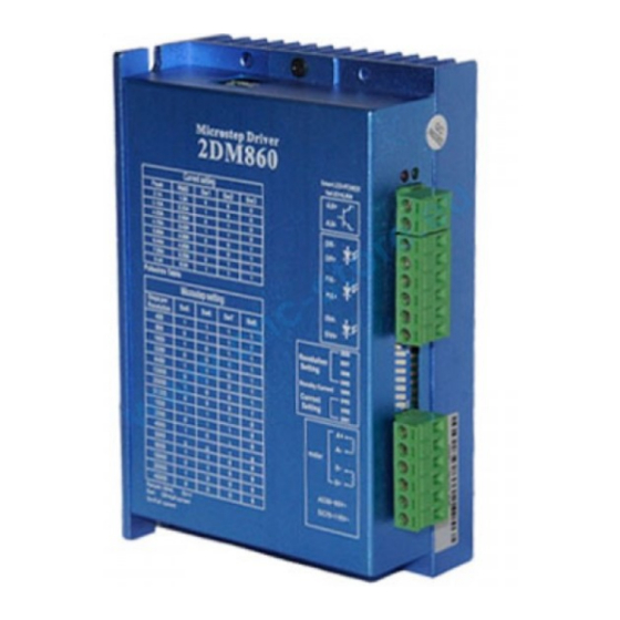
Page 18: Appearance And Installation Dimensions
Shenzhen Just Motion Control Electro-mechanics Co., Ltd 0755-26509689 8. Appearance and Installation Dimensions - 18 -... -
Page 19: Typical Connection
Shenzhen Just Motion Control Electro-mechanics Co., Ltd 0755-26509689 9. Typical Connection Here is the typical connection of 2DM860H. - 19 -... -
Page 20: Parameter Setting
0755-26509689 10. Parameter Setting The parameter setting method of 2DM860H drive is to use a HISU adjuster through the 232 serial communication ports, only in this way we can set the parameters we want. There are a set of best default... - Page 21 Shenzhen Just Motion Control Electro-mechanics Co., Ltd 0755-26509689 Reserved Command Type 0—1 User-defined micro 4—1000 steps Time of standstill 0—4000 1000 current Percentage of 0—100 standstill current Speed smoothness 0—10 Enable of position 0—1 memory User-defined 0—100 resistance of motor User-defined 0—100 inductance of motor...
- Page 22 Damping coefficient in case of the desired operating state is coefficient under resonance frequency.This parameter is useful in high speed. 2DM860H Driver provides robust anti-resonance control to stop the vibrations and maintain Amp 1—3 equilibrium. Phase 1—3 Amp1 and Phase1 is Phase adjustment for 1st and Amplitude adjustment for 1st resonance area respectively.
- Page 23 Shenzhen Just Motion Control Electro-mechanics Co., Ltd 0755-26509689 Amp2 and Phase2 is Phase adjustment for 2nd and Amplitude adjustment for 2nd resonance area respectively. Usually between 1.2rps and 2.4rps. Anti-resonance This parameter is used for reducing resonance. coefficient Usually between 3rps and 4rps. Enable signal This parameter is set to control the Enable input level...
- Page 24 Enable of position position memory. 0 means disable, while 1 means memory enable. If set 1, the 2DM860H can remember the position of motor in the next time of power on. This parameter is set the resistance of motor. 0...
-
Page 25: Processing Methods To Common Problems And Faults
Shenzhen Just Motion Control Electro-mechanics Co., Ltd 0755-26509689 This parameter is set the inductance of motor. 0 User-defined means 2DM860H gets the inductance by control inductance of algorithm of Parameter auto-setup, while 1 means motor 2DM860H gets the inductance through user sets. -
Page 26: After Input Pulse Signal But The Motor Not Running
Shenzhen Just Motion Control Electro-mechanics Co., Ltd 0755-26509689 11.4 After input pulse signal but the motor not running Please check the input pulse signal wires are connected in reliable way. Please make sure the input pulse mode is corresponding with the real ...
Need help?
Do you have a question about the 2DM860H and is the answer not in the manual?
Questions and answers