Advertisement
ASKOHEAT
‐F+
Fitting instructions, user manual and service
Please keep in a safe place
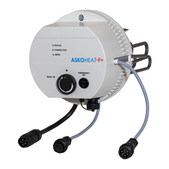
Flange heater Ø 180mm
for industrial and hea ng water
AHFR‐BI‐plus‐1.75 up to 5.8 kW
AHIR‐BI‐plus‐1.75
AHIR‐BI‐plus‐3.5
AHIR‐BI‐plus‐4.4
AHIR‐BI‐plus‐5.8
Index
General safety and assembly informa on
Opera ng instruc ons
Assembly instruc ons
User manual
Opera ng condi ons
Electrical diagram
Service
Malfunc on
ASKOHEAT
‐F+
Flange heater Ø 180mm
MVGASV_012‐6791_V01_en
www.askoma.com
Page 2
Page 3
Page 4
Page 6
Page 7
Page 8 / 9
Page 10
Page 10
Page 1
Advertisement
Table of Contents

Related Manuals for ASKOMA ASKOHEAT-F+


Summary of Contents for ASKOMA ASKOHEAT-F+
- Page 1 Page 8 / 9 Service Page 10 Malfunc on Page 10 ASKOHEAT MVGASV_012‐6791_V01_en www.askoma.com Page 1 ‐F+...
-
Page 2: General Safety Information
The device must be installed horizontally, an installa on from above or below is not permi et for safety reasons. Make sure that the hea ng tubes are en rely covered by the liquid before placing into opera on. The circula on of the liquid shall not be inhibited. Opera ng data, applica on, dimensions and model of the flange heater are on the iden fica on plate and circuit diagram on the device, respec vely inside the housing cover, or can be found in the fi ng instruc ons / user manuals. ASKOHEAT MVGASV_012‐6791_V01_en www.askoma.com Page 2 ‐F+... - Page 3 I n t h e e v e n t o f t h e f o l l o w i n g t h e g u a r a n t e e i s v o i d : ‐ Not complying with this paperwork „Fi ng instruc ons, user manual, and service“ ‐ Not complying with the storage heater manufacturer's fi ng instruc ons ‐ Technical modifica ons, repairs or tampering with the device (including exchanging the thermostat) ‐ Applica ons for which the device was not designed ‐ Incorrect opera on and maintenance ‐ Not complying with direc ve VDI 2035 ‐ Manipula ons on the opera ng so ware ‐ Undocumented parameteriza ons via the documented interfaces ASKOHEAT MVGASV_012‐6791_V01_en www.askoma.com Page 3 ‐F+...
- Page 4 T i g h t e n t h e s c r e w s w i t h a t o r q u e w r e n c h F i l l t h e t a n k a n d c h e c k f o r l e a k s ASKOHEAT MVGASV_012‐6791_V01_en www.askoma.com Page 4 ‐F+...
- Page 5 Connec on 1: GND Connec on 2: Heat pump request Connec on 3: Analogue input 0‐10V Connec on 4: RS485: A Connec on 5: RS485: B Connec on 6: RS485: GND ‐ Plug Z4— LAN connec on via data cable and RJ45 socket ASKOHEAT MVGASV_012‐6791_V01_en www.askoma.com Page 5 ‐F+...
- Page 6 ASKOHEAT automa cally switches back to normal opera on a er 24 hours. ‐F+ Safety: EN60335‐1 / ‐2‐21 / ‐2‐73 A p p l i c a b l e EMC: EN55014‐1 / ‐2 CEM: EN62233 s t a n d a r d s IP Code: EN60529 ASKOHEAT MVGASV_012‐6791_V01_en www.askoma.com Page 6 ‐F+...
-
Page 7: Operating Conditions
ASKOHEAT Flange heater Ø 180mm ‐F+ Operating conditions L E D 1 : S TAT U S Green Connec on to a control device (e.g. ASKOMA energy manager) via Modbus TCP Yellow Hea ng mode (when connected to control via Modbus TCP) Red Hea ng mode (without connec on to control device) Blue Legionella protec on is ac ve White ... -
Page 8: Electrical Diagram
ASKOHEAT Flange heater Ø 180mm ‐F+ Electrical diagram All power supply circuits must have been switched off before accessing WARNING! the connec on terminals. Electrical and connec on diagram 1.75 kW AHFR‐BI‐plus‐1.75 ASKOHEAT MVGASV_012‐6791_V01_en www.askoma.com Page 8 ‐F+... - Page 9 ASKOHEAT Flange heater Ø 180mm ‐F+ Electrical diagram All power supply circuits must have been switched off before accessing WARNING! the connec on terminals. Electrical and connec on diagram 3.5 kW ‐ 5.8 kW AHFR‐BI‐plus‐3.5 AHFR‐BI‐plus‐4.4 AHFR‐BI‐plus‐5.8 ASKOHEAT MVGASV_012‐6791_V01_en www.askoma.com Page 9 ‐F+...
- Page 10 Needs cleaning Malfunction If the safety temperature Reset limiter trips, there is a fault or error. A qualified expert See user manual for the must inspect the system in qualified installer. this case. The version currently valid can be downloaded under "Downloads" from our homepage For technical data see the data sheet Subject to technical altera ons ASKOHEAT MVGASV_012‐6791_V01_en www.askoma.com Page 10 ‐F+...
Need help?
Do you have a question about the ASKOHEAT-F+ and is the answer not in the manual?
Questions and answers