ASKOMA ASKOHEAT+ AHIR-BI-plus-1.75 Fitting Instructions, User Manual And Service
Screw-in heater r 1 1/2“ for drinking and heating water
Hide thumbs
Also See for ASKOHEAT+ AHIR-BI-plus-1.75:
- Fitting instructions, user manual and service (10 pages) ,
- User manual (10 pages)
Advertisement
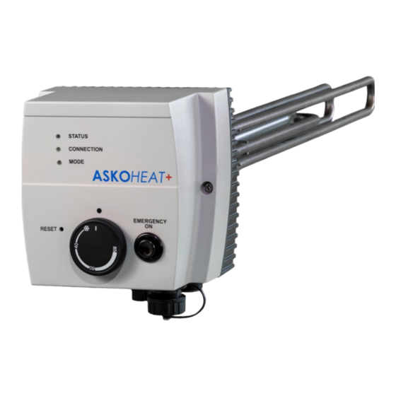
ASKOHEAT+
Fitting instructions, user manual and service
Please keep in a safe place
Screw-in heater R 1½" for drinking and hea ng water
1.75 to 5.2 kW
AHIR-BI-plus-1.75
AHIR-BI-plus-3.5
AHIR-BI-plus-4.4
AHIR-BI-plus-5.2
Index
General safety and assembly informa on
Opera ng instruc ons
Assembly instruc ons
User manual
Opera ng condi ons
Electrical diagram
Service
Malfunc on
ASKOHEAT+
Insulated moun ng
Screw-in heater R 1½"
MVGASV_012-6391_V02_en
www.askoma.com
Page 2
Page 3
Page 4
Page 5
Page 6
Page 7 / 8
Page 9
Page 9
Page 1
Advertisement
Table of Contents

Related Manuals for ASKOMA ASKOHEAT+ AHIR-BI-plus-1.75


Summary of Contents for ASKOMA ASKOHEAT+ AHIR-BI-plus-1.75
- Page 1 Insulated moun ng ASKOHEAT+ Screw-in heater R 1½“ Fitting instructions, user manual and service Please keep in a safe place Screw-in heater R 1½“ for drinking and hea ng water 1.75 to 5.2 kW AHIR-BI-plus-1.75 AHIR-BI-plus-3.5 AHIR-BI-plus-4.4 AHIR-BI-plus-5.2 Index General safety and assembly informa on Page 2 Opera ng instruc ons Page 3 Assembly instruc ons Page 4 User manual Page 5 Opera ng condi ons Page 6 Electrical diagram Page 7 / 8 Service Page 9 Malfunc on Page 9 ASKOHEAT+ MVGASV_012-6391_V02_en www.askoma.com Page 1...
-
Page 2: General Safety Information
Make sure that the hea ng tubes are en rely covered by the liquid before placing into opera on. The circula on of the liquid shall not be inhibited. Opera ng data, applica on, dimensions and model of the screw-in heater are on the iden fica on pla te and circuit diagram on the device, respec vely inside the housing cover, or can be found in the fi ng instruc ons / user manuals. ASKOHEAT+ MVGASV_012-6391_V02_en www.askoma.com Page 2... - Page 3 I n t h e e v e n t o f t h e f o l l o w i n g t h e g u a r a n t e e i s v o i d : - Not complying with this paperwork „Fi ng instruc ons, user manual, and service“ - Not complying with the storage heater manufacturer's fi ng instruc ons - Technical modifica ons, repairs or tampering with the device (including exchanging the thermostat) - Applica ons for which the device was not designed - Incorrect opera on and maintenance - Not complying with direc ve VDI 2035 - Manipula ons on the opera ng so ware - Undocumented parameteriza ons via the documented interfaces ASKOHEAT+ MVGASV_012-6391_V02_en www.askoma.com Page 3...
- Page 4 Connec on 1: Temperature sensor 1 Connec on 2: Temperature sensor 2 Connec on 3: Temperature sensor 3 Connec on 4: Temperature sensor 4 Connec on 5: Connec on 6: Relay K4 - Plug Z3—Heat pump request / 0-10V analogue signal (op onal) Connec on 1: Connec on 2: Heat pump request Connec on 3: Analogue input 0-10V Connec on 4: RS485: A Connec on 5: RS485: B Connec on 6: RS485: GND ASKOHEAT+ MVGASV_012-6391_V02_en www.askoma.com Page 4...
- Page 5 ASKOHEAT+ automa cally switches back to normal opera on a er 24 hours. Safety: EN60335-1 / -2-21 / -2-73 A p p l i c a b l e EMC: EN55014-1 / -2 CEM: EN62233 s t a n d a r d s IP Code: EN60529 ASKOHEAT+ MVGASV_012-6391_V02_en www.askoma.com Page 5...
-
Page 6: Operating Conditions
L E D 2 : C O N N E C T I O N Connec on to local network (LAN) Green LAN (Ethernet) connected to a switch, hub or router Yellow-flashing Data communica on over LAN (Ethernet) Blue-flashing ASKOHEAT+ is running without LAN connec on, e.g. using only analog input L E D 3 : M O D E Yellow Heater relais are ac ve, but without current flow (switch-off by thermostat) Green Heater is ac ve with current flow Blue-flashing Emergency Mode is ac ve White Iden fy for 20 seconds or Emergency Mode toggles on or off / very fast flashing at start and stop update ASKOHEAT+ MVGASV_012-6391_V02_en www.askoma.com Page 6... -
Page 7: Electrical Diagram
Insulated moun ng ASKOHEAT+ Screw-in heater R 1½“ Electrical diagram All power supply circuits must have been switched off before accessing WARNING! the connec on terminals. Electrical and connec on diagram 1.75 kW AHIR-BI-plus-1.75 ASKOHEAT+ MVGASV_012-6391_V02_en www.askoma.com Page 7... - Page 8 Insulated moun ng ASKOHEAT+ Screw-in heater R 1½“ Electrical diagram All power supply circuits must have been switched off before accessing WARNING! the connec on terminals. Electrical and connec on diagram 3.5 kW - 5.2 kW AHIR-BI-plus-3.5 AHIR-BI-plus-4.4 AHIR-BI-plus-5.2 ASKOHEAT+ MVGASV_012-6391_V02_en www.askoma.com Page 8...
- Page 9 The build up of scale in the hea ng element can lead to the ac va on of the safety temperature limiter or thermal overloading thereby destroying the hea ng elements. In such cases the guarantee is not valid! 1. 2. The device must be cleaned (descaled) with a suitable professional descaling agent, e. g. citric acid. Needs cleaning Malfunction If the safety temperature Reset limiter trips, there is a fault or error. A qualified expert See user manual for the must inspect the system in qualified installer this case. The version currently valid can be downloaded under "Downloads" from our homepage For technical data see the data sheet Subject to technical altera ons ASKOHEAT+ MVGASV_012-6391_V02_en www.askoma.com Page 9...
Need help?
Do you have a question about the ASKOHEAT+ AHIR-BI-plus-1.75 and is the answer not in the manual?
Questions and answers