Table of Contents
Advertisement
Quick Links
ASKOHEAT
+ 2.0
Installation instructions, user manual and service
Please keep in a safe place
Screw-in heater R 1½" for drinking and heating water
1.75 to 9.0 kW
•
AHIR-TI-plus-1.75
•
AHIR-TI-plus-3.5
•
AHIR-TI-plus-4.4
•
AHIR-TI-plus-5.2
•
AHIR-TI-plus-7.5
•
AHIR-TI-plus-9.0
Index
MV-012-6801.2
Isolated installation
Screw-in heater R 1½"
-RC+
01.04.2024
www.askoma.com
Page 2
Page 3
Page 4 / 5
Page 6
Page 7
Page 8
Page 9
Page 10
Page 11
Page 12
Page 13
Page 14
Page 1
Advertisement
Table of Contents

Related Manuals for ASKOMA ASKOHEAT+ 2.0


Summary of Contents for ASKOMA ASKOHEAT+ 2.0
-
Page 1: Table Of Contents
Corrosion protection / Start-up Page 9 Functional description Page 10 Electrical diagram 1.75 kW Page 11 Electrical diagram 3.5 — 5.2 kW Page 12 Electrical diagram 7.5 — 9.0 kW Page 13 Service / Malfunction Page 14 MV-012-6801.2 01.04.2024 www.askoma.com Page 1... -
Page 2: General Safety And Installation Advice
/ user manual. Safety: EN60335-1 / -2-21 / -2-73 Applicable EMV: EN55014-1 / -2 EMF: EN62233 standards IP Code: EN60529 MV-012-6801.2 01.04.2024 www.askoma.com Page 2... -
Page 3: Installation Guidelines
- Applications for which the device was not designed - Incorrect operation and maintenance - Not complying with directive VDI 2035 - Manipulations of the operating software - Undocumented parameterizations via the documented interfaces MV-012-6801.2 01.04.2024 www.askoma.com Page 3... -
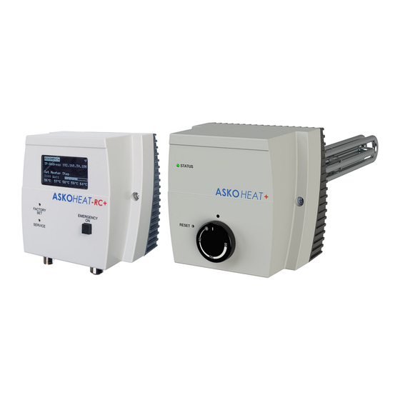
Page 4: Device Description
The "Factory Set" button can be used to reset the device to the factory settings. All settings made are then deleted. Service A permanent IP address can be assigned to the device using the "Service" button. The IP address is then 192.168.222.222. MV-012-6801.2 01.04.2024 www.askoma.com Page 4... - Page 5 If the safety temperature limiter is activated, it can be reset with a "00 screwdriver" through the ope- ning labelled "Reset". This is only possible once the temperature has cooled down by approx. 10 K. MV-012-6801.2 01.04.2024 www.askoma.com Page 5...
-
Page 6: Installation Instructions For Control Device Askoheat -Rc
If the control unit has to be installed on a pipe or on the hot water tank, use the required additional material. Detailed instructions are enclosed with the accessories. The additional material can be ordered from your supplier using the Askoma article number 012-2264. MV-012-6801.2 01.04.2024... -
Page 7: Installation Instructions For Screw-In Heaters
- Connector Z1—Connect the power supply with the heater with the connector as shown below: Connection 1: Connection 2: Connection 3: Connection N: Connection PE: - Connect the ASKOHEAT control housing with the included connection cable: -RC+ Connection RJ12 socket -> to the ASKOHEAT Connection X1 -RC+ MV-012-6801.2 01.04.2024 www.askoma.com Page 7... -
Page 8: Connector And Connections Assignment
Connection 2: Sensor 1 Connection 3: Connection 4: Sensor 2 Connection 5: Connection 6: Sensor 3 Connection 7: Connection 8: Sensor 4 Connector Modbus RTU RS485 Connection 1: Connection 3: RS485 B Connection 4: RS485 A MV-012-6801.2 01.04.2024 www.askoma.com Page 8... -
Page 9: Corrosion Protection / Start-Up
+ 2.0 (correctly), the IP address can be read off the display of the ASKOHEAT -RC+ Example: 192.168.0.23 -> then enter this in the browser as follows: http://192.168.0.23 MV-012-6801.2 01.04.2024 www.askoma.com Page 9... -
Page 10: Functional Description
The heater ignores all other signals and heating commands. This function is used, for example, for heat pumps to be able to cool in summer. Or to prevent the ap- pliance from heating despite a PV surplus. MV-012-6801.2 01.04.2024 www.askoma.com Page 10... -
Page 11: Electrical Diagram 1.75 Kw
Isolated installation ASKOHEAT + 2.0 Screw-in heater R 1½“ Electrical diagram All power supply circuits must have been switched off before accessing WARNING! the connection terminals. Electrical and connection diagram 1.75 kW • AHIR-TI-plus-1.75 MV-012-6801.2 01.04.2024 www.askoma.com Page 11... - Page 12 Screw-in heater R 1½“ Electrical diagram All power supply circuits must have been switched off before accessing WARNING! the connection terminals. Electrical and connection diagram 3.5 - 5.2 kW • AHIR-TI-plus-3.5 • AHIR-TI-plus-4.4 • AHIR-TI-plus-5.2 MV-012-6801.2 01.04.2024 www.askoma.com Page 12...
-
Page 13: Electrical Diagram 3.5 - 5.2 Kw
All power supply circuits must have been switched off before accessing WARNING! the connection terminals. Electrical and connection diagram 7.0 - 9.0 kW • AHIR-TI-plus-7.5 • AHIR-TI-plus-9.0 Included connection cable 2.0 m Cable cross-section: 2.5 mm² MV-012-6801.2 01.04.2024 www.askoma.com Page 13... -
Page 14: Service / Malfunction
See user manual the system must be checked for the specialist. by a specialist. The version currently valid can be downloaded from our homepage For technical data see the data sheet Subject to technical alterations MV-012-6801.2 01.04.2024 www.askoma.com Page 14...
Need help?
Do you have a question about the ASKOHEAT+ 2.0 and is the answer not in the manual?
Questions and answers