ASKOMA ASKOHEAT-F+ AHFR-BI-plus-5.8 Fitting Instructions, User Manual And Service
Flange heater ø 180mm for drinking and heaɵng water
Hide thumbs
Also See for ASKOHEAT-F+ AHFR-BI-plus-5.8:
Advertisement
ASKOHEAT
‐F+
Fitting instructions, user manual and service
Please keep in a safe place
Flange heater Ø 180mm
for drinking and hea ng water
AHFR‐BI‐plus‐1.75 up to 5.8 kW
AHFR‐BI‐plus‐1.75
AHFR‐BI‐plus‐3.5
AHFR‐BI‐plus‐4.4
AHFR‐BI‐plus‐5.8
Index
General safety and assembly informa on
Opera ng instruc ons
Assembly instruc ons
User manual
Opera ng condi ons
Electrical diagram
Service
Malfunc on
MV‐012‐6791.2
Flange heater Ø 180mm
01.04.2023
www.askoma.com
Page 2
Page 3
Page 4
Page 6
Page 7
Page 8 / 9
Page 10
Page 10
Page 1
Advertisement
Table of Contents

Related Manuals for ASKOMA ASKOHEAT-F+ AHFR-BI-plus-5.8


Summarization of Contents
General safety and assembly information
General Safety Information
General safety precautions and user responsibilities for operating the device safely.
Assembly Information
Device must be installed horizontally. Ensure heating tubes are covered by liquid.
Operating instructions
Temperature Control Limits
Controller must limit heat exchanger temperature to 85°C to prevent tripping.
Safety Temperature Limiter Reset
Safety temperature limiter may trip at low temperatures; reset button is on page 6.
Usage Restriction
The device may only be used to heat water.
Corrosion Protection Settings
Select DIP switch settings based on boiler type (black steel or stainless steel).
Electrical Connection Requirements
Fixed connection only, suitable cable cross-section, 3mm isolating distance, PE wire longer.
Warranty Void Conditions
Violating manual, improper use, unauthorized modifications, or non-compliance voids warranty.
Assembly instructions
Physical Mounting Procedure
Steps include unscrewing cover, cleaning flange, screwing heater, tightening screws, filling tank.
Electrical Connections
Connect power supply (Z1), temperature sensor (Z2), and heat pump/0-10V signal (Z3) using specified plugs.
User manual
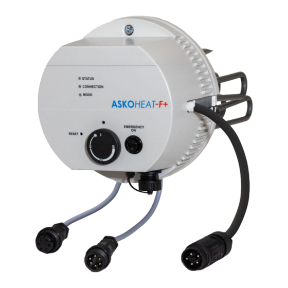
Device Description and Controls
Overview of ASKOHEAT-F+ features, including Modbus interface, analogue input, and buttons.
Temperature Control Operation
Maximum temperature adjusted via rotary knob (0-85°C), economic setting at 65°C.
Safety Temperature Limiter Reset
Tripped safety limiter can be reset via 'Reset' opening after cooling.
Emergency Operation Mode
Activate 'Emergency On' for max output for 24 hours, limited to 55°C.
Applicable Standards
Lists relevant safety, EMC, and IP code standards the device complies with.
Operating conditions
LED Status Indicators
Explanation of LED meanings for Status, Connection, and Mode (colors and flashing patterns).
Electrical diagram
1.75 kW Diagram and Connections
Wiring diagram for 1.75 kW models, showing power supply, plugs Z1, Z2, Z3, and RJ45.
3.5 kW - 5.8 kW Diagram and Connections
Wiring diagram for 3.5-5.8 kW models, showing power supply, plugs Z1, Z2, Z3, and RJ45.
Service
Regular Descaling
Descaling recommended 2x/year, especially in hard water areas, to prevent damage and voiding warranty.
Cleaning Procedure
Device must be cleaned (descaled) using a suitable descaling agent like citric acid.
Malfunction
Troubleshooting Safety Limiter
If safety temperature limiter trips, it indicates a fault requiring inspection by a qualified expert.
Reset Procedure
Refer to user manual for qualified installer regarding reset procedures for malfunctions.
Need help?
Do you have a question about the ASKOHEAT-F+ AHFR-BI-plus-5.8 and is the answer not in the manual?
Questions and answers