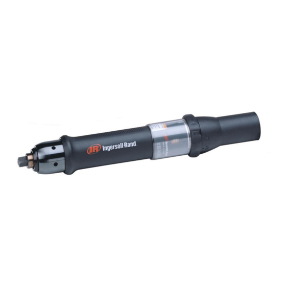
Ingersoll-Rand QE4 Series Maintenance Information
Electric angle wrench
Hide thumbs
Also See for QE4 Series:
- Instructions manual (52 pages) ,
- Maintenance information (8 pages) ,
- Product information (124 pages)
Summary of Contents for Ingersoll-Rand QE4 Series
- Page 1 16575151 Edition 1 June 2006 Electric Angle Wrench QE4 Series Maintenance Information Save These Instructions...
-
Page 2: General Instructions
General Instructions: • Refer to “Suggested Tools Parts List” for quick reference Lubrication to the tools recommended for the following disassembly/ Whenever this product is disassembled, clean the parts and assembly instructions. re-lubricate them as follows: 1. Clean and degrease all parts except for the 1st and 2nd WARNING Stage Spindle Assemblies (45, 43). - Page 3 In-Line Attachments Motor Temperature-Sensor Socket 1. For 3/8” Square Drive Spindles, Locate Retaining Pin (57) and Retaining Spring (56) of Spindle’s square socket. Motor Phases Connector If necessary, use a pointed metal probe to pull Retaining Spring out of Spindle cavity. Also, if necessary, remove Pin from Square Drive Spindle (54).
- Page 4 11. Carefully slide the Transducer Gear Pack Assembly out 2. Gently pull Transducer Gear Pack Assembly out of the of the Motor Housing Assembly while ensuring clearance Motor Housing Assembly, feeding the Transducer wire for wire assemblies between the spline teeth of the through the holes in the Motor Housing Assembly.
- Page 5 Transducer Gear Pack Assembly Installation 10. Thread Coupling Nut (73 or 74) onto Motor Housing Assembly. (For In-Line and Angle Wrench Models) 11. While holding the tool using a Hook Spanner or similar 1. Orient the Spacer located in the Motor Housing Assembly wrench, use a Spanner Wrench to torque Coupling Nut to groove at the bottom of the spline, so that the opening in 15 - 20 lbf •...
-
Page 6: Internal Components
In-Line Attachment - Installation Motor Temperature-Sensor Socket 1. Position the In-Line Attachment appropriately. 2. Engage the spline on the input spindle of the In-Line Motor Phases Connector Attachment with the matching internal spline of the Spindle Assembly (43), then engage the spline on the Housing Assembly with the internal spline of the Motor Housing Assembly and thread the Coupling Nut onto the Motor Housing. -
Page 7: Parts And Maintenance
QE4 Series Wiring (Cable) Chart Connector Pin Wire Color (Cable) Logic Connector Pin Black Gray Spare 1 Pink Spare 2 Brown Spare 4 Yellow Sine Orange Cosine Violet Spare 3 Green Ground Sense Blue Blue/White White White/Blue Motor Phase B... - Page 8 www.irtools.com Ingersoll Rand © 2006 Company...


Need help?
Do you have a question about the QE4 Series and is the answer not in the manual?
Questions and answers