Table of Contents
Advertisement
Quick Links
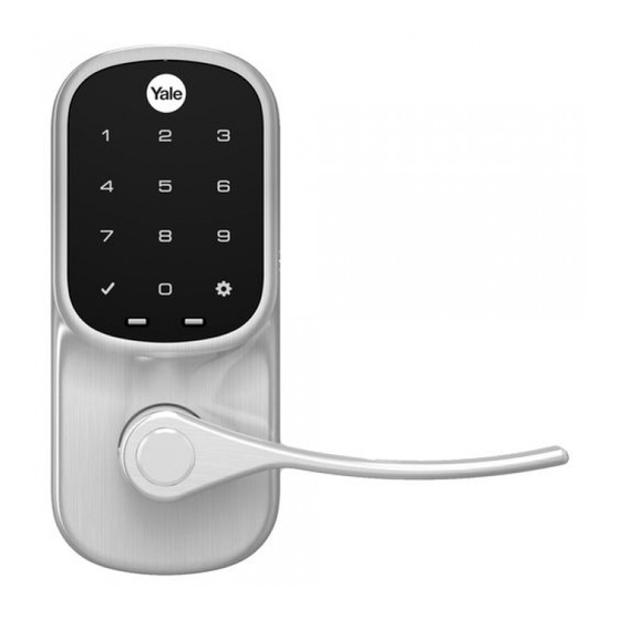
Yale Assure Lock Lever Push Button
®
®
Installation and Programming Instructions
®
(YRL216)
x2
#8-32 x 5/16"
Machine screws
x4
x2
#7 wood & #8-32
machine x 20mm
M4 x 22mm
Combination screws
Pan head machine
screws
AA Alkaline
Template
Batteries
Battery Cover
Key
Levers
Latch
Before you begin
Cylinder
DOWNLOAD
THE BILT APP
Optional
for step-by-step installation
Network Module
instructions & to register
Strike Plate
Battery Cover
your product
WARNING
This product can expose you to lead which is known to the state of
Keys
Interior Mounting Plate
California to cause cancer and birth defects or other reproductive harm.
Interior Lock
For more information go to www.P65warnings.ca.gov.
1
FAILURE TO FOLLOW THESE INSTRUCTIONS COULD RESULT IN DAMAGE TO THE PRODUCT AND VOID THE FACTORY WARRANTY
P/N YRL-LPBINSTL-FUL Rev C
Advertisement
Table of Contents
Troubleshooting

Related Manuals for Assa Abloy Yale Assure Lock Lever


Summary of Contents for Assa Abloy Yale Assure Lock Lever
- Page 1 Yale Assure Lock Lever Push Button ® ® Installation and Programming Instructions ® (YRL216) #8-32 x 5/16" Machine screws #7 wood & #8-32 machine x 20mm M4 x 22mm Combination screws Pan head machine screws AA Alkaline Template Batteries Battery Cover...
- Page 2 Preparing to Install Tools Needed Standard Phillips Head Screwdriver Tools necessary only for new doors or adjusting existing prep. Template Tape Pencil Measure Drill Wood Mortise Chisel Utility Knife Level 2-3/8" through bolt posts default *Backset PULL 2-3/4" through bolt posts Note: Adjustment based on backset *2-3/8"...
- Page 3 Checking Measurements 2-3/8" or 2-3/4" (60mm or 70mm) Backset 2-1/8" (54mm) Diameter 1-3/8" or 1-3/4" (35mm or 44.5mm) Door Thickness Door Prep Template P/N YRL-LPBINSTL-FUL Rev C...
- Page 4 Determining Door Handing Inswinging Door Outswinging Door Interior Left Hand Right Hand Interior Reverse Reverse Left Hand Right Hand Exterior Exterior Face a door swinging open Face a door swinging open away from you. toward you. If it swings open to the right, If it swings open to the right, it it is a right hand door.
- Page 5 Preparing Door & Frame Necessary for new doors or adjusting existing prep. 2-1/8" Door Prep (54mm) Template Dia. 2-3/8" (60mm) 1" (25mm) 2-3/4" (70mm) Dia. Backset Drill holes 1/2 way through door then complete from other side to prevent splitting. Frame Frame Inside...
- Page 6 Installing Latch & Strike Plate Right Hand Installation Shown Outside of Door Frame P/N YRL-LPBINSTL-FUL Rev C...
- Page 7 Installing Push Button Right Hand Installation Shown “TOP” mark must be on top surface and tailpiece in vertical position. Incorrect orientation will cause lock to fail. Outside of Right Hand Door Inside of Right Hand Door P/N YRL-LPBINSTL-FUL Rev C...
- Page 8 Installing Interior Mounting Plate Right Hand Installation Shown Inside of Right Hand Door Inside of Right Hand Door P/N YRL-LPBINSTL-FUL Rev C...
- Page 9 Attaching the Cable Assembly Right Hand Installation Shown Inside of Right Hand Door P/N YRL-LPBINSTL-FUL Rev C...
- Page 10 Installing Interior Lock Right Hand Installation Shown Inside of Right Hand Door “Click” P/N YRL-LPBINSTL-FUL Rev C...
- Page 11 Installing Exterior Cylinder Outside of Right Hand Door Latch Cylinder must be installed with bar away from latch. P/N YRL-LPBINSTL-FUL Rev C...
- Page 12 Installing Exterior Lever Outside of Right Hand Door Press pin while installing lever so lock is not damaged. Installing Interior Lever Inside of Right Hand Door Press pin while installing lever so lock is not damaged. P/N YRL-LPBINSTL-FUL Rev C...
- Page 13 Testing Thumbturn Operation Test with door open. Outside of Right Hand Door Outside of Right Hand Door If thumbturn operation test fails, check installation beginning with Step 3. P/N YRL-LPBINSTL-FUL Rev C...
- Page 14 Testing Key Operation Test with door open. Outside of Right Hand Door Outside of Right Hand Door If key operation test fails, check installation beginning with Step 6. P/N YRL-LPBINSTL-FUL Rev C...
- Page 15 Installing Optional Network Module Inside of Right Hand Door NOTE: If a network module was included with your lock, it is in a separate box with additional module installation instructions. P/N YRL-LPBINSTL-FUL Rev C...
- Page 16 Installing Batteries & Cover Inside of Right Hand Door Congratulations, you've installed the ® ® Yale Assure Lock Lever Push Button ( YRL216 Programming Instructions will help you customize your product. P/N YRL-LPBINSTL-FUL Rev C...
- Page 17 Testing Push Button Operation Test with door open. A Master PIN Code must be created upon installation or after resetting the lock to factory default. Programming and use of lock is not possible until this step has been successfully completed. See of Programming Instructions below.
- Page 18 Resetting Lock to Factory Default Interior Lock Reset Button When resetting the lock, all user codes, including the Master PIN code*, are deleted. All programming features are reset to original default settings. See “Factory Settings”. 1. Remove the battery cover and batteries. 2.
- Page 19 Changing Lock: Replacing Cylinder 1.To Remove cylinder: See installation Step 6 "Installing Exterior Lever" and reverse appropriate actions to remove the exterior lever handle and cylinder. 2.To install new cylinder: A. Follow appropriate actions of installation Step 6 "Installing Exterior Lever"...
- Page 20 Hardware Troubleshooting Cycle lock in both the locked and unlocked positions. If problems are found: Tailpiece and spindle will not mate and fit into the interior escutcheon a. Ensure that your door is between 1-3/8" and 1-3/4" thick b. Ensure that the square shaped spindle has “Top” writing and arrow facing upwards c.
- Page 21 Programming Instructions Speaker Master PIN Code must be created before any further programming. Max User Codes = 250 with Network Module. Max User Codes = 25 without. P/N YRL-LPBINSTL-FUL Rev C...
- Page 22 Creating Master PIN Code Creating a Master PIN Code must be performed upon installation or after resetting the lock to factory default. Programming and use of lock is not possible until this step has been successfully completed. Press Press Press Enter 4-8 digit Master PIN Code.
- Page 23 Creating User PIN Codes Master PIN code must be created first. *Max user codes = 250 with Network Module. Max user codes = 25 without. Enter Master PIN code Press Press Enter 4-8 digit PIN code Press Press Press Press (code flashes) Adding more User Codes: To end programming:...
- Page 24 Unlocking Door with PIN Code Enter PIN Code Press Code Chart Duplicate if necessary PIN Code Management PIN Code (With Network Module Up to 250 Users) Master: User Name: P/N YRL-LPBINSTL-FUL Rev C...
- Page 25 Definitions All Code Lockout Mode: This feature is enabled by the Master code. When enabled, it restricts all user (except Master) PIN code access. When attempting to enter a code while the unit is in Lockout, the RED locked padlock will appear on the screen. Audio Mode: The audio setting for PIN code verification is set to Enable (1) by default;...
- Page 26 Feature Programming Through Menu Mode Using Master PIN code* 1. Enter 4-8 digit master PIN code* followed by key. 2. Enter digit corresponding to the function to be performed followed by the key. *The Master PIN code must be created prior to any other programming of the lock. Master PIN Code Setting User PIN Code Registration Register...
- Page 27 Programming Troubleshooting Symptom Suggested Action * When batteries are replaced, Smart Module locks have a real time clock that will be set through the User Interface (UI); it is recommended to verify correct date and time particularly those locks operating under Daylight Saving Time (DST). P/N YRL-LPBINSTL-FUL Rev C...
- Page 28 Ÿ Consult the dealer or an experienced radio/TV technician for help. Ÿ Warning: Changes or modifications to this device, not expressly approved by ASSA ABLOY Residential Group could void the user's authority to operate the equipment. Industry Canada: This Class A digital apparatus meets all requirements of the Canadian Interference Causing Equipment Regulations.
- Page 29 Yale Z-Wave Plus Smart Module ® ® ® Installation Guide Please use this procedure only when network primary controller is missing or otherwise inoperable. Adding a Yale Z-Wave Plus Smart Module to your Assure Lock & Z-Wave System ® 1. Install the Yale Smart Module into the slot above the battery compartment IMPORTANT: The batteries must be removed before removing the Yale Smart Module: •...
- Page 30 CAN ICES-3B/NMB-3B 24/7 Tech Support : 1-855-492-0505 • www.yalehome.com Yale® is a registered trademark of ASSA ABLOY Residential Group. Other products' brand names may be trademarks or registered trademarks of their respective owners and are mentioned for reference purposes only. © Copyright 2019. All rights reserved. Reproduction in whole or in part without the...
- Page 31 Yale ZigBee Module ® ® ® Installation and Programming Instructions Installing the ZigBee Module ® IMPORTANT: the batteries must be removed prior to removing and/or inserting the network module: • Remove battery cover. • Remove batteries. • Remove and/or insert network module. •...
- Page 32 Yale Locks & Hardware is a division of Yale Security Inc., an ASSA ABLOY Group company. Yale® and Yale Real Living® are registered trademarks of Yale Security Inc., an ASSA ABLOY Group Company. Other products’ brand names may be trademarks or registered trademarks of their respective owners and are mentioned for reference purposes only.
Need help?
Do you have a question about the Yale Assure Lock Lever and is the answer not in the manual?
Questions and answers