Table of Contents
Advertisement
Quick Links
Advertisement
Table of Contents

Subscribe to Our Youtube Channel
Related Manuals for BE HW3513HAD


Summary of Contents for BE HW3513HAD
- Page 1 HOT WATER PRESSURE WASHER HW3513HAD User Manual BEPOWEREQUIPMENT...
-
Page 2: Table Of Contents
TABLE OF CONTENTS TABLE OF CONTENTS Safety Parts List 6 Safety Rules 30 Specifications 7 Safety Warnings 32 Flow Chart 32 EMF System Features 33 Operation Theory 12 Features 34 Frame Assembly Installation & Preparation 36 Engine/Pump Assembly 13 Attire 38 High Pressure Pump 13 Set-Up 41 Unloader/Manifold Assembly 14 Engine/Burner Fuel Tank 42 ... - Page 3 Record Identification Numbers manual prior to the initial use of your Pressure Washer Pressure Washer If you need to contact an Authorized Dealer or Customer Service line (1- 866-850-6662) for information on servicing, always provide the product model and identification numbers. Using the Operator’s manual You will need to locate the model and serial number for the pump and The operating manual is an important part of your Pressure Washer. It record the information in the places provided below. should be read thoroughly before initial use, and referred to often to make sure adequate safety and service concerns are being addressed. Date of Purchase: Reading the owner’s manual thoroughly will help avoid any personal injury or damage to your pump. By knowing how best to operate this machine Dealer Name: you will be better positioned to show others who may also operate the Dealer Phone: unit. You can refer back to the manual at any time to help troubleshoot any specific operating functions, so store it with the machine at all times.
-
Page 4: Safety
• Never fill the fuel tanks while the pressure washer is running or hot. Follow safety messages to avoid or reduce the risk of injury or death. Allow to cool two minutes before refueling. • Always refuel slowly to avoid the possibility of spilled fuel which may Hazard Symbols and Meanings cause a risk of fire. • Do not refuel indoors or in a poorly ventilated area. • Engine Fuel Tank: Refuel with gasoline only. Do not use diesel or fuel oil. • Burner Fuel Tank (Black): When refueling the Burner Fuel Tank, use No. 1 or No. 2 fuel oil/diesel or kerosene. Do not use gasoline. • Do not operate the unit if diesel fuel is spilled. Wipe the pressure explosion fire hot surface moving parts washer clean and move it away from the spill. Avoid creating any ignition until the diesel fuel has evaporated. • A spark arrester must be added to the muffler of this engine if it is to be used on any forest covered, brush covered or grass covered unimproved land. The arrester must be maintained in effective working order by the operator. In the state of California, the above is required electric flying objects toxic fumes injection by law. (Section 4442 of the California Public Resources Code.) shock Other states may have similar laws. Federal laws apply on Federal lands. • This pressure washer has a Safety Relief device which should never be altered, modified, removed or made inoperative. If the device fails, replace immediately with only genuine manufacturer replacement part. - Page 5 WARNING WARNING Serious injury or death may occur from inhaling engine/ burner exhaust or dangerous vapors. The engine Serious injury or death may occur from contact with exhaust from this product contains chemicals known to electricity. the State of California to cause cancer, birth defects, or other reproductive harm. • DO NOT direct spray on or into electrical installations of any kind! • Never operate this pressure washer in an enclosed area. Always make This includes electrical outlets, light bulbs, fuse boxes, transformers, certain there is adequate ventilation (fresh outside air) for breathing the unit itself, etc. and combustion. This will prevent the buildup of dangerous carbon • DO NOT allow metal components of the pressure washer to come in monoxide gases. Beware of poorly ventilated areas, or areas with contact with live electrical components. exhaust fans which can cause poor air exchange. • Follow all safety instructions provided with the materials you are spraying. Use of a respirator may be required when working with WARNING some materials. Do not use this pressure washer to dispense Serious injury may occur from touching the gasoline hazardous detergents. engine, muffler or heat exchanger. These areas can remain hot for some time after the pressure washer is shutdown. WARNING • Never allow any part of your body to contact the gasoline engine, muffler or heat exchanger. Serious injury or death could occur from high pressure spray penetrating the skin. WARNING • Keep clear of nozzle and spray! Never put your hand, fingers or body directly over the spray nozzle. Serious injury may occur from a pressure washer • Do not direct discharge stream at persons or self. malfunction or exploding accessories if incorrect • This product is to be used only by trained operators.
- Page 6 SAFETY SAFETY WARNING • NEVER trigger the gun while on a ladder or roof. • ALWAYS hold on firmly to the gun/lance assembly when starting and Serious injury may occur to the operator from moving operating the unit. Failure to do so can cause the lance to fall and parts on the pressure washer. whip dangerously. • Know how to stop the pressure washer and bleed pressures quickly. • Before making any adjustments, be certain the engine is turned off Be thoroughly familiar with controls. and the ignition cable(s) is removed from the spark plug(s). Turning • DO NOT leave pressurized unit unattended. Shut off the pressure the machinery over by hand during adjustment or cleaning might start washer and release trapped pressure before leaving. the engine and machinery with it. • DO NOT operate the unit if you see any fuel, oil or water leaks from • Do not operate the unit without all protective covers in place. the machine. DO NOT resume operation until the unit has been in- spected and repaired by a qualified service person. • NEVER run the engine with the governor disconnected or operate at WARNING excessive speeds. • Place unit in a clean, dry, flat area for servicing. Before servicing the Serious injury or death may occur from detergents con- unit: turn the unit off, relieve the water pressure from the trigger gun, tacting the skin. and allow the unit to cool down. Service in clean, dry, flat area. If ap- plicable, block wheels to prevent unit from moving. Serious injury can occur from loose debris being pro- • Do not move the unit by pulling on the hose. pelled at a high speed from the spray gun. Injury may occur if the operator loses his balance caused by the thrust of water traveling through the WARNING: This product can expose you to spray nozzle.
-
Page 7: Features
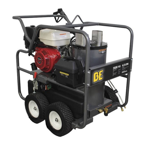
BELTGUARD FLAT FREE WHEELS Proper attire is essential to your safety. It is advised to utilize whatever GASOLINE ENGINE TANK BURNER ON/OFF SWITCH AIR SHUTTER ADJUSTING ARM means necessary to protect eyes, ears, and skin. Additional safety BURNER FUEL TANK HEAT EXCHANGER EXHAUST attire (such as respiratory mask) may be required when using detergent HIGH PRESSURE HOSE TRIGGER SAFETY LOCK TRIGGER GUN cleaning agents with this washer. DUAL LANCE QUICK CONNECT NOZZLE SET-UP 1. This unit should only be placed on a level surface to ensure proper lubrication for the water pump while operating. NEVER spray water ... -
Page 8: Engine/Burner Fuel Tank
2. The 15° nozzle (YELLOW): This is a chiseling nozzle. The spray should gasoline may be used if lead-free is unavailable. DO NOT use gasoline or items attached with adhesive backings. Uses: Removing weeds be directed at a 45° angle to the surface and used like a scraper to remove containing methanol or alcohol. from sidewalk cracks, stubborn stains from concrete, masonry, alumi- paint, grease and dirt. Uses: Surface preparation (removing mildew stains 5. Check the engine oil level before starting the engine. (See Engine ... -
Page 9: Nozzle Review
1. The 0° nozzle (RED): This is a blasting nozzle. It delivers a very concentrated • When connecting the water inlet to the water supply mains, local be directed at a 45° angle to the surface and used like a scraper to remove stream of water. Be cautious when using the straight narrow stream. It is first two digits indicate the spray fan in degrees, i.e.;... -
Page 10: Thermal Relief Valve
INSTALLATION & PREPARATION OPERATION Operating Instructions THERMAL RELIEF VALVE To ensure the water temperature does not exceed acceptable levels, PRIMING THE PUMP never allow the pressure washer to operate in the bypass mode (with the It is essential to prime the pump and flush the unit each time the water unit running and the trigger closed) for more than three minutes. supply has been disconnected from the unit OR whenever the unit has set for any period of time. This unit has a steel coil which, after setting, A “thermal relief valve” has been added to this unit to protect the pump. will cause the water remaining in the coil from the previous usage to It may begin to open and release water if the water temperature in the turn brown or black. This contaminated water must be flushed from the pump has exceeded 140° F. This will allow fresh, cool water to enter the system before start-up. This procedure should be performed without the system. high pressure hose, gun and nozzle assembly installed. PRE-START INSPECTION PROCEDURES 1. Turn on the water supply. Before starting the unit, perform the following procedures: 2. Low pressure water will begin flowing from the water outlet. This al- lows the unit to prime and purge any air from the system. The unit is 1. Check the oil level in the pump and engine. primed when water flow is uninterrupted by air. 2. Inspect the water inlet strainer. Clean or replace if necessary. See 3. Once the system is flushed, turn off the water supply and connect the “Water Supply”, #2, pg 16. high pressure discharge hose/gun to the water outlet of the unit. 3. Check all hose connections to ensure they are securely tightened. See ... -
Page 11: Hot Water Operation
OPERATION OPERATION 1. Refer to the “Safety Precautions” pgs. 7-11 before starting the unit. HOT WATER OPERATION 2. Locate the Safety Decals on your unit and heed their warnings. 3. Ensure that the switch is in the “OFF” position. WARNING 4. Perform the following engine start-up procedures. THE WATER TEMPERATURE COULD BECOME VERY HOT DURING a. Point the trigger gun in a safe direction, disengage the safety lock HOT WATER OPERATION. BE CAUTIOUS WHEN ADJUSTING on the gun and squeeze the trigger. PRESSURE OR CONTROLLING THE TRIGGER GUN/ LANCE b. Brace yourself for kickback from the high pressure created by the ASSEMBLY. pump once the engine has started. c. Hold the trigger gun open while starting the engine according to the 1. Follow the steps outlined for “START-UP/COLD WATER manufacturer’s instructions in the engine manual accompanying this OPERATION”. unit. 2. Move the Burner Switch to the ON position. On initial start-up, water 5. Once the unit has started, perform the following procedures with the will begin turning hot in approximately 20 seconds and will reach gun open: maximum temperature in approximately 2-1/2 minutes, provided the a. Inspect for system water leaks, oil leaks and fuel leaks. If a fuel leak trigger remains squeezed. The burner will stop firing when the trigger is found, TURN UNIT OFF IMMEDIATELY! See “Risk of Explosion is released. or Fire”, pg. 7. Be sure that all damaged parts are replaced and that the mechanical problems are corrected prior to operation of the At this point, the unit is operating as a hot water pressure washer. Be unit. If you require service, contact Customer Service. extremely cautious when adjusting the pressure and controlling the b. Inspect high pressure hoses for kinking, cuts and leaks. If a cut or trigger gun/ lance assembly to avoid the possibility of burns. leak is found, DO NOT TOUCH HOSE AT LEAK!!! TURN UNIT OFF ... -
Page 12: Shutdown
Combustion will begin again when the temperature drops below the minimum setting. connect the desired high pressure nozzle into the end of the wand. making it larger, resulting in a pressure loss. Nozzles should be point, the unit is operating as a hot water pressure washer. Be certain to remely cautious when adjusting the pressure and controlling the trigger Unlock the trigger gun and spray. It will take about 30 seconds to nce assembly to avoid the possibility of burns. -
Page 13: Winterizing
MAINTENANCE MAINTENANCE 5. Repeat steps 2 and 3 until step 4 is attained. h. Holding the 3 foot hose in an upright position, completely fill the hose with water. Then plug the open end of the hose with your thumb LEAKS: Promptly eliminate any leaks found in the pumping system by or finger. Place the plugged end into the 5 gallon container of water. removing suspect parts, applying thread sealant to the threads and i. Start the unit. Trigger the gun several times until all the air is worked reinstalling. out of the system (unit is primed). j. With the trigger gun held open, siphon enough water out of the 5 NOTICE gallon container until there is just enough water left to mix with the If using Teflon tape, be certain no tape gets inside any plumbing to antifreeze. prevent the possibility of a plugged spray nozzle. k. Point the trigger gun into the empty container. (Be certain to wear safety attire for protection from splashing.) l. Trigger the gun until the antifreeze begins to exit the trigger gun. WINTERIZING Release the trigger for 3 seconds, then trigger the gun for 3 seconds. 1. For storage and transportation purposes in subfreezing ambient tem- Continue cycling the trigger gun several times until all the antifreeze peratures, it will be necessary to winterize this unit. This unit must be mixture is siphoned from the container. protected to the lowest incurred temperature for the following reasons: m. Stop the unit. a. If any part of the pumping system becomes frozen; excessive n. Detach the 3 foot hose from the unit and drain any excess antifreeze pressure may build up in the unit which could cause the unit to burst back into the 5 gallon container storage & maintenance resulting in possible serious injury to the operator or bystanders. o. Disconnect the hose and trigger gun from the unit and drain any b. The pumping system in this unit may be permanently damaged if excess antifreeze back into the 5 gallon container. frozen. FREEZE DAMAGE IS NOT COVERED BY WARRANTY. p. Drain hose, trigger gun and lance assembly and store with the unit in a safe non-freezing area. If you must store your unit in an area where the temperature may fall ... -
Page 14: Maintenance Chart
Obstructed or worn spray Remove, clean or replace. nozzle. Test water temperature* Damaged or obstructed Remove, clean or replace. Descale coil**** valve assy. on pump. Pump packings worn. Replace packings. * Must be performed by an authorized service technician. Unloader/Bypass valve not Repair or replace. ** The pump oil must be changed after the first 50 hours of operation operating correctly. and every 250 hours or 3 months, whichever comes first. Water is leaking from Water temperature is too Do not allow unit to operate in *** High pressure nozzle should be replaced whenever pressure is less Thermal Relief Valve. high. bypass mode (with the trigger than 85%. gun closed) for more than three **** Scale build-up will vary with mineral content in the water and minutes. amount of usage. Descaling can range from weekly to yearly Defective valve. Replace. maintenance. Oil appears milky or Water in oil. Change pump oil. Fill to proper ***** The engine oil must be changed after the first 8 hours of operation foamy. level. and every 50 hours or 3 months, whichever comes first. - Page 15 Ignition electrodes With unit running and trigger Pressure Detergent detergent solution. damaged or worn. gun closed, look through burner mode. Detergent strainer Inspect, clean or replace. sight glass to ensure there is obstructed. sparking across electrodes. Detergent hose cut, Inspect, clean or replace. No voltage Consult your Customer Service. obstructed or kinked. Pressure switch override. Pressure should be over 250 Detergent adjusting knob Open adjusting knob. Refer to PSI/18 Bar to allow burner to turned to closed position. “Cleaning with Detergents”. come on. Too many high pressure Use one extension maximum. High limit switch override. Unit will automatically reignite hose extensions attached to when cool. the water outlet. Improper burner air Adjust as explained on page 26. Nozzle assembly is plugged. Clean or replace. adjustment. Ball & Spring in Venturi Remove, clean or replace.
-
Page 16: Parts List
PARTS LIST PARTS LIST Parts List SPECIFICATIONS CONT. SPECIFICATIONS MODEL NUMBER HW3513HAD Fuel Consumption (GPH/LPH) 2.1 GPH Continous Burning MODEL NUMBER HW3513HAD Electro Magnetic Firing (EMF) System: Belt Driven (Patent #5,954,494) Operating Pressure (PSI/Bar) 3500 / 241 (+/- 5%) Ignition Transistorized Magneto Water Volume (GPM/lpm) 3.27 / 12.38 (+/- 5%) Control Voltage 12 Volt DC Outlet Water Temperature (F/C) 140°F/78°C (+/- 20°F) rise above inlet ambient (210°F/ 99°C maximum) Blower Forced Air Engine: Honda Heat Exchanger: Vertical, Top fi red, Dual Spiral Coil Model GX390 BTU Input 294,000 Engine Type Four Stroke, Overhead Cam, Single Cylinder Effi ciency... -
Page 17: Flow Chart
PARTS LIST PARTS LIST FLOW CHART EMF SYSTEM FLOW CHART GENERAL THEORY OF OPERATION WATER FLOW: Connect a pressurized water source to the INLET GAR- DEN HOSE CONNECTION (1) and turn on the water supply. The water then travels into the TRIPLEX HIGH PRESSURE PUMP (2) which has an UNLOADER (6) that bypasses the water when the trigger gun is closed. To protect the pump from heated water during this bypass stage, a HEAT DUMP VALVE (5) will open at 140°F/60°C allowing the heated water to escape. The Heat Dump Valve automatically resets when the water cools. The PRESSURE SWITCH (7) controls the fuel supply to the burner. From there, the water will flow into the HEAT EXCHANGER INLET (10) where it is heated when the burner is on. As the water exits the HEAT EXCHANGER OUTLET (11), it enters a safety system which protects the operator from danger. The safety system contains a HIGH TEMPERA- TURE LIMIT SWITCH (12) which senses the water temperature and shuts off the fuel supply to the burner if it gets too hot. If the unloader fails to bypass the water or the burner remains on when the trigger gun is closed, the SAFETY RELIEF (13) will relieve and allow water to exit safely. EMF SYSTEM FLOW CHART EMF SYSTEM The heated water then flows through the HIGH PRESSURE HOSE (14) and to the TRIGGER GUN ASSEMBLY (15) which allows the operator to control the water spray. When the trigger gun is open, the water flows ... -
Page 18: Frame Assembly
PARTS LIST PARTS LIST FRAME ASSEMBLY FRAME ASSEMBLY SPECS REC'D: DATE: ITEM DESCRIPTION PART # Hose Reel Mounting Bracket 20-1395A42 Washer 28-0003 Bolt 27-0072 Heat Exchanger / Emf Assy Bolt 27-9524 Locknut 30-0155 Bolt 27-1201 29 28 Brake Bracket 20-1393A01 Bolt 27-0015 Bolt 27-9550 Push/Pull Toggle Clamp 33-0400 Engine Shim 33-0169 Bolt 27-9529 30-3023 13 12... -
Page 19: Engine/Pump Assembly
PARTS LIST PARTS LIST ENGINE/ PUMP ASSEMBLY ENGINE/PUMP ASSEMBLY ENGINE/PUMP ASSEMBLY ITEM DESCRIPTION PART # Engine - Honda GX390 Recoil 1-0205 Washer 28-0605 Oil Drain 24-0143 Adapter Flange 38-0049 Bolt 27-0418 Sheave 10-0077 Belt 11-0037 43-0088 Bolt 27-8434 Adapter Plate 38-0051 High Pressure Hose 15-0194 Elbow 23-0034 Relief Valve 22-0005 Pressure Switch 22-0171 Plug 23-0244... -
Page 20: High Pressure Pump
PARTS LIST PARTS LIST HIGH PRESSURE PUMP (3-0194) HIGH PRESSURE PUMP ITEM DESCRIPTION PART # Connecting Rod (after serial #28511) 46-0922 Connecting Rod (before serial #28511) 46-0697 Piston Pin 46-0698 Plunger Rod 46-0699 Slinger Washer (see kit 70-0352) 46-0700 Back-up Ring (see kit 70-0352) 25-0404 O-Ring (see kit 70-0352) 25-0382 Piston (see kit 70-0352) 46-0701 Washer (see kit 70-0352) 26-0191 30-6020 Oil Dipstick 39-0090 Bearing Cap 46-0703 Shim - 0.1mm (qty. varies 1-3) 46-0704 Shim - 0.2mm (qty. varies 1-3) 46-0705 O-Ring (see kit 70-0337) 25-0380... -
Page 21: Unloader/Manifold Assembly
PARTS LIST PARTS LIST UNLOADER/MANIFOLD ASSEMBLY UNLOADER/MANIFOLD ASSEMBLY ITEM DESCRIPTION PART # Valve Spring (see kit 70-0179) N/A Sep. Valve Cage (see kit 70-0179) N/A Sep. Plug 39-0096 O-Ring 25-0387 Bolt 27-8440 Lockwasher 29-0154 REPLACEMENT KITS KIT # DESCRIPTION ITEMS # OF # OF ASSEBLIES CYLINDERS 70-0177 Kit - High Pressure 34, 35, 37 Seals 70-0178 Kit - Support Rings 70-0179 Kit - Valve Kit 46-50 70-0337 Kit - Oil Seals Kit 3, 4, 17, ... -
Page 22: Unloader
PARTS LIST PARTS LIST PRESSURE SWITCH (22-0171) UNLOADER PRESSURE SWITCH ITEM DESCRIPTION PART # VENDOR PFHMS - M6-1.00 x 8mm (SEE KIT 70-0647) 27-2772 B13001 SEE KIT ITEM KNOB - UNLOADER BLACK (SEE KIT 70-0647) DESCRIPTION PART # 7-0250 B13002 SEE KIT KNOB - M20-1.00P (SEE KIT 70-0647) B13003 SEE KIT... -
Page 23: Detergent Injector
PARTS LIST PARTS LIST DETERGENT INJECTOR (50-0052) DETERGENT INJECTOR HEAT EXCHANGER/EMF SYSTEM HEAT EXCHANGER/EMF SYSTEM ITEM DESCRIPTION PART # Pressure Relief Valve 22-0273 ITEM DESCRIPTION PART # QC Socket 17-0004 Detergent Injector (inc. 2-11) 50-0052 Pipe Nipple 24-*0165 Orifice (2.1mm) 50-0057 Outlet Connector 24-0138 Injector Body HI Limit Switch 32-0798 Spring (see 852-0056) N/A Sep. Drain Plug Assembly 850-0218 Ball (see 852-0056) N/A Sep. -
Page 24: Boiler Assembly
PARTS LIST PARTS LIST BOILER ASSEMBLY ITEM DESCRIPTION PART # BOILER ASSEMBLY (850-0226) HP Fuel Hose 15-0165 ELECTRODE GAP SETTINGS Elbow 23-0288 Fuel Solenoid 44-0100 Bolt 27-9524 Elbow 23-0237 Fuel Hose 15-0147 Fuel Filter/Water Separator 19-0070 Nipple 24-0145 Fuel Pump 3-0020 Idler Pin 33-0211 Tensioner Sheave Shaft Assembly 850-0166 Locknut 30-0159 Sheave Assembly 850-0177 Idler Shaft 33-0212... -
Page 25: Gun/Wand/Hose Assembly
PARTS LIST PARTS LIST GUN /WAND/HOSE ASSEMBLY GUN/WAND/HOSE ASSEMBLY ITEM DESCRIPTION PART # Bolt 27-8879 Air Diverter 20-0378A01 30-0137 Star Washer 28-1009 Air Diverter Stem 20-0377A01 Plug 24-0034 30-0121 Washer 28-0521 Outer Wrap 20-0376A42 Insulation 33-0250 Heat Exchanger Coil 66-0011 Inner Pan Assembly 20-0372 Top Pan 20-0371A01 Lockwasher 28-1028 Acorn Nut 30-6002 ITEM DESCRIPTION PART #... -
Page 26: Dual Lance Assembly
PARTS LIST PARTS LIST DUAL LANCE ASSEMBLY (16-0416) FUEL TANK (850-0193) DUAL LANCE ASSEMBLY FUEL TANK FUEL TANK (850-0193) FUEL TANK ITEM DESCRIPTION FUEL CAP FUEL GAUGE ITEM DESCRIPTION PART # FUEL GAUGE GROMMET FUEL PICK UP Fuel Cap 12-0033 NIPPLE DECAL - CAUTION: RISK OF FIRE (SEE 71 Fuel Gauge 22-0475 ELBOW... -
Page 27: Fuel Pump & Fuel Solenoid
PARTS LIST PARTS LIST FUEL PUMP (3-0020) & FUEL SOLENOID (44-0100) FUEL PUMP (3-0020) & FUEL SOLENOID (44-0100) EMF SYSTEM (850-0403) FUEL PUMP & FUEL SOLENOID EMF SYSTEM 0MHSP049-080902-BAR FUEL PUMP (3-0020) & FUEL SOLENOID (44-0100) 0MHSP049-080902-BAR REF. # DESCRIPTION PART # QTY. -
Page 28: Electric Box Assembly
PARTS LIST PARTS LIST ELECTRIC BOX ELECTRIC BOX ASSEMBLY ITEM DESCRIPTION PART # EMF Assembly 850-0403 Blower Fan 44-0099 Set Screw Locknut 30-0177 Blower Flange Assembly 850-0402 Sealed Bearing 48-0041 Blower Flange 38-0066 Spacer 33-0206 Blower Shaft 20-0347 Woodruff Key 43-0080 ITEM DESCRIPTION PART # Clamp 32-0403 Electric Box Hardware Kit 70-0169 Screw 27-2070 Screw 27-3350 Stator Assembly... -
Page 29: Statement Of Warranty
WIRING SCHEMATIC PARTS LIST WARRANTY WIRING SCHEMATIC STATEMENT OF WARRANTY The manufacturer warrants all parts, (except those referred to below), of your new pressure washer to be free from defects in materials and work- manship during the following periods: For Lifetime against freezing and cracking: Pump Manifold For Seven (7) Years from the date of original purchase: WIRING DIAGRAM High Pressure Pump For Three (3) Years from the date of original purchase: WIRING DIAGRAM Heat Exchanger Coil For Two (2) Years from the date of original purchase: Frame Plumbing Guard or Shields Pulleys For One (1) Year from the date of original purchase: Adjustable Thermostat GFCI Cord Selector switch Starter Contactor Overload For Six (6) months from the date of original purchase: Ignition Transformer Burner Motor For Ninety (90) days from the date of original purchase: Unloader Valve Electrodes Fuel solenoid High Limit thermostat Fuel Pump Pressure Switch Safety Relief Valve For Thirty (30) days from the date of original purchase: High Pressure Hose Trigger Gun Strainers / Filters Wand Defective parts not subject to normal wear and tear will be repaired ... -
Page 30: Warranty Exclusions
WARRANTY WARRANTY EXCLUSIONS 1. The motor is covered under separate warranty by its respective manufacturer and is subject to the terms set forth therein. 2. Normal wear parts: Pump Packings Spray Nozzles Pump Valves Detergent Valves Fuel Filters Quick Couplers/screw connects O-rings Belts 3. This warranty does not cover parts damaged due to normal wear, misapplication, misuse, operation at other than recommended speeds, pressures or temperature. Parts damaged or worn because of the use of caustic liquids or by operation in abrasive or corrosive environments or under conditions causing pump cavitation are not warranted. Failure to follow recommended operating and maintenance procedures also voids warranty. 4. The use of other than Genuine Repair Parts will void warranty. Parts returned, prepaid to our factory or to an Authorized Service Center will be inspected and replaced free of charge if found to be defective and subject to warranty. There are no warranties which extend beyond the description of the face hereof. Under no circumstances shall the manufacturer bear any responsibility for loss of use of the unit, loss of time or rental, inconvenience, commercial loss or consequential damages. - Page 31 THE POWER YOU NEED. If you need assistance with the assembly or operation of your Pressure Washer please call 1-866-850-6662...
Need help?
Do you have a question about the HW3513HAD and is the answer not in the manual?
Questions and answers