
Related Manuals for BE Commercial Series


Summary of Contents for BE Commercial Series
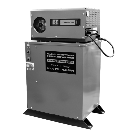
- Page 1 NATURAL GAS ALL ELECTRIC PRESSURE WASHER X-HW3075EW3GEN Operator Manual 85.610.618...
-
Page 2: Table Of Contents
TABLE OF CONTENTS Introduction & Product Info Optional Accessories Introduction & Product Specifications 20 Types of Accessories for your Pressure Washer Important Safety Warnings Maintenance Important Safety Warnings & Symbols Protecting System from Freezing Maintenance Chart Getting to Know Your Washer Wiring Diagrams Product Features &... -
Page 3: Introduction & Product Info
Thank you for purchasing our hot water pressure washer! This operating manual is an important part of the unit. It should be read thoroughly before initial use, and referred to often to make sure adequate safety and service concerns are being addressed. -
Page 4: Important Safety Warnings
Keep open sparks and flames away from the battery at all times, especially when charging. • Be certain to disconnect the battery ground terminal before servicing. When disconnecting the cable from the battery, start with the negative terminal. When connecting them, start with the positive cable. -
Page 5: Important Safety Warnings & Symbols
Serious injury or death may occur if system safety’s are not properly maintained. • A spark arrester must be added to the muffler of this engine when using on land covered with any flammable agricultural crop (hay and grain), and if they are used in or near brush or forested areas. The arrester must be maintained in effective working order by the operator of the equipment. - Page 6 • Use only manufacturer recommended repair parts for your pressure washer. • In freezing temperatures, the unit must always be warm enough to ensure there is no ice formation in the pump. Do not start the pressure washer if it has been transported in an open or under heated vehicle without first allowing the pump to thaw.
-
Page 7: Getting To Know Your Washer
GETTING TO KNOW YOUR WASHER Belt driven pump Pressure Gauge for increased reliability and longevity Adjustable pressure regulator c/w oversized bypass hose Premium Efficiency Triplex Belt Drive Inverter-Duty Motor General Pump with a 5 year warranty Automatic high Low water level temperature shutdown indicator light (Pump protection) -
Page 8: Before Starting The Unit
WARNING This system must be protected from freezing at all times. Do not install the equipment in areas where it may be exposed to temperatures below 0°C (32°F). PORTABLE SYSTEMS / WHEEL KITS... -
Page 9: Connecting To Water Supply
The recommended screen size for most applications be 25 to 30 PSIG (1.4 to 2 bar) above the water is 80 mesh. supply pressure. The discharge port of the relief... - Page 10 Do not adjust or override the pressure switch or jam the reset button in an attempt to prevent system stalling. Severe system damage will result. NOTE: The LWPP circuit will have to be reset after any interruption in the power supply to the machine.
-
Page 11: Connecting To Electrical Supply
Pressure Protection circuit, which links a pressure WARNING All electrical work is to be performed by qualified and licensed personnel only. The installation must comply with all local codes and laws applying to this type of device. This machine must be electrically grounded. -
Page 12: High Pressure Connection
WARNING Only mating halves of quick couplers pressure rated to match the system should be used to make high- pressure connections. Mixing of various couplers may result in system damage or personal injury. - Page 13 CLS cleaning stations. STARTING THE PRESSURE WASHER Before Starting the Pressure Washer • Be sure that the inlet and discharge hoses are attached and that all connections are secure. • Check that the water supply is turned on and there are no leaks in the system.
- Page 14 This position is intended for overriding the disconnected.
-
Page 15: System Pressure Adjustments
/ unloader valve in an attempt and failure. The correct nozzle number has been to restore lost pressure. If the pressure must be provided at the front of this manual. Keep this adjusted, a high quality liquid filled pressure gauge... -
Page 16: Lubrication
Some larger capacity pumps may have seal lubricating ports or oilers. The lubricating ports will be located on the top of the pump crankcase at the front edge close to the manifold. Under normal use, three (3) drops of oil per month is sufficient in each port. -
Page 17: Chemical Soap Application
WARNING Regular checks of the chemical supply tank will be required. Always be sure that the tank is at an ample level and that the pick up end of the chemical tube is submerged in the chemical at all times. Damage to the system may result if air is allowed to enter the system via the chemical tube. - Page 18 To select either toward or pushing away from the trigger gun will nozzle, close the trigger gun and rotate the gun /...
-
Page 19: Chemical Rate Adjustments
With the knob in the full in (closest damage. to the body of the injector), no chemical will be allowed into the water stream. Turning the knob out 3. Adjust the fine metering screw until the desired (away from the body of the injector) amount of chemical is achieved. -
Page 20: Optional Accessories
OPTIONAL ACCESSORIES When selected, cleaning in chemical mode will reduce the pressure at that drop by approximately 35%. A supply of chemical will have to be provided Pressure Gauge at the CS1. Mating quick connects matching the CLS If added as a factory installed option, a glycerin filled and the high-pressure hose are provided on the CS1. - Page 21 Always grip the hose firmly when un-spooling or spooling. Do not allow the hose to rewind freely. Be sure that your feet and legs will not become entangled in the hose as it rewinds. The hose must have an unobstructed path to the reel...
- Page 22 (0˚ pattern) can be clicking of the ratchet stops. Maintaining a tight grip time consuming. To resolve both of these issues, a on the hose, allow it to slowly retract.
-
Page 23: Maintenance
To maintain the free flow of abrasive, the pick up damaging heat build up on the surface being tube, or probe as it may be referred to, requires air cleaned. to be available where the sand enters. Tube designs... - Page 24 **** Scale build-up will vary with mineral content in the water and amount of usage. Descaling can range from weekly to yearly maintenance. ***** The engine oil must be changed after the first 8 hours of operation and then every 50 hours or 3 months, whichever comes first.
-
Page 25: Wiring Diagram
WIRING DIAGRAM 17 | P a g e © c o p y r i g h t P S C . A l l i n f o r m a t i o n c o n t a i n e d h e r e i n s u b j e c t c h a n g e... -
Page 26: Wiring Diagram Legend
WIRING DIAGRAM LEGEND ITEM DESCRIPTION DETAIL PSC OPTION PART NO. High-pressure Pump See attached data sheet Pressure Regulator / Unloader See attached data sheet See attached data sheet (IF Safety Relief Valve USED) Flow Switch See attached data sheet Pressure Gauge Liquid Filled / 0 - 100 PSI Pressure Gauge Liquid Filled / 0 - 4000 PSI... -
Page 27: Pumping System
This regulator also allows water flow from the pump water inlet connection via a water hose supply to be recirculated (known as the bypass) back into line. The supply line requires a minimum 3/4” male the inlet when the gun is closed. A thermo safety garden hose connection. -
Page 28: Heat Exchanger
HEAT EXCHANGER HEAT EXCHANGER The design feature of our Heat Exchanger allows high pressure cold water to be heated in an unpressurized tank. Cold water entering the heat exchanger passes through a coil submerged in heated water. Electrical controls for the exchanger and pumping package are mounted on the outside of the tank. -
Page 29: Heat Exchanger Connections
CAUTION Before pumping package is started for the first time, or after maintenance has been performed on any supply or discharge water lines, all air must be purged from the system. Failure to do so may result in system damage. - Page 30 HEAT EXCHANGER DIAGRAM 72 kW Heat Exchanger High Pressure Connectors EP41 Pan Cover** EP33 Tank Wrap** (modified with holes) EP32 Insulation EP14 Tank Filler plug** EP40 Stainless Steel Coil Assembly EP38 Tank Low Level Switch Insulation EP26 EP14 Electrical Panel** EP30 Tank Filler Tube** Thermostat**...
-
Page 31: Electrical Panel Assembly Legend
ELECTRICAL PANEL ASSEMBLY DIAGRAM LEGEND ITEM DESCRIPTION DETAIL PART NO. Terminal Strip Control circuit 202324 Timer Solid state 8 sec delay off 400441 Din Bar Motor contactor mounting 202567 3.5” Motor over-load see table 1 below Dual coil 1/2 in 4000 PSI 316 SS *400574 Ground lug 70 AMP... - Page 32 ELECTRICAL PANEL ASSEMBLY DIAGRAM LEGEND ITEM DESCRIPTION DETAIL PART NO. EP33 Top Cover 12B exchanger (black) 400104 EP34 Dual heater top cover 12B-2 dual heater (black) *100650BLCK EP35 Electric panel cover 8C panel cover (black single) 400098 EP36 Electric panel cover 8C-2 panel cover (black dual) *100077BLCK EP37...
- Page 33 ELECTRICAL PANEL ASSEMBLY EP 4 Relay, Motor Over-Load Motor Voltage 208/3 Phase 230/3 phase 575 – 600/3Phase 460 - 480/3 Phase 400483 401360 401467 401468 401465 401466 401359 401359 401337 400483 / 400483 401360 / 403899 Motor 401283 401466 400483 Horse 401481 401471 / 403905...
- Page 34 ELECTRICAL PANEL ASSEMBLY EP 11 Fuse, Motor Circuit Motor Voltage 208/3 Phase 230/3 phase 575 – 600/3Phase 460 - 480/3 Phase 202715 20 amp FLNR 20 202721 10 amp NLS 10 202721 10 amp NLS 10 202719 25 amp FLNR 25 202438 15 amp FLSR 15 202438 15 amp FLSR 15 400893 35 amp FLNR 35...
- Page 35 ELECTRICAL PANEL ASSEMBLY EP 21 Transformer Supply Voltage 208/3 Phase 230/3 Phase 575 – 600/3Phase 460 - 480/3 Phase 400325 PH50MLI 400116 PH50AR 402523 PH100MLI 400545 PH100AR Transformer PH150MLI PH150AR PH200MLI PH200AR PH250MLI PH250AR Table 9 EP 28 Element Supply Voltage 208/3 Phase 230/3 Phase 460 - 480/3 Phase...
- Page 36 ELECTRICAL DIAGRAM 26 | P a g e © c o p y r i g h t P S C . A l l i n f o r m a t i o n c o n t a i n e d h e r e i n s u b j e c t c h a n g e...
-
Page 37: Pump Parts
PUMP PARTS 28 | P a g e © c o p y r i g h t P S C . A l l i n f o r m a t i o n c o n t a i n e d h e r e i n s u b j e c t c h a n g e... -
Page 38: Troubleshooting
• Worn main bearing(s) from excessive tension • Replace bearing(s) and/or belts. pulley. on drive belt. • Change oil/ Use any high-grade automotive • May be caused by humid air condensing 30 weight non-detergent oil inside the crankcase Water in crankcase. • Replace packing •... -
Page 39: Warranty
ALL BE PRESSURE WASHERS COME WITH A COMPREHENSIVE WARRANTY ON PRIMARY PARTS SUCH AS ENGINES, PUMPS, AND PRODUCTS. BE Power Equipment warrants that each new product will be free of any manufacturer defects in workmanship frames. See below for details specific to your BE product for the set warranty period of the product. - Page 40 if you need assistance with the assembly or operation of your pressure washer please call 1-866-850-6662 or visit our website...
Need help?
Do you have a question about the Commercial Series and is the answer not in the manual?
Questions and answers