Navien NFC-175 Installation & Operation Manual
Nfc condensing combi-boilers
Hide thumbs
Also See for NFC-175:
- Service manual (138 pages) ,
- User's information manual (26 pages) ,
- Quick installation manual (4 pages)
Table of Contents
Advertisement
Installation & Operation Manual
NFC Condensing Combi-Boilers
Model
NFC-175
NFC-200
NSF/ANSI 372
H
WARNING
If the information in these instructions is not followed exactly, a fire or explosion may result, causing
property damage, personal injury, or death.
Do not store or use gasoline or other flammable vapors and liquids in the vicinity of this or any other
appliance.
WHAT TO DO IF YOU SMELL GAS
Do not try to light any appliance.
●
Do not touch any electrical switch; do not use any phone in your building.
●
Immediately call your gas supplier from a neighbor's phone. Follow the gas supplier's instructions.
●
If you cannot reach your gas supplier, call the fire department.
●
Installation and service must be performed by a qualified installer, service agency or the gas
supplier.
The installation must conform with local codes or, in the absence of local codes, the National Fuel
Gas Code, ANSI Z223.1/NFPA 54 and/or CSA B149.1, Natural Gas and Propane Installation Code.
Keep this manual near this boiler for future reference
whenever maintenance or service is required.
* The wetted surface of this product contacted by consumable water contains less than
one quarter of one percent (0.25%) of lead by weight.
Advertisement
Table of Contents

Related Manuals for Navien NFC-175


Summary of Contents for Navien NFC-175
- Page 1 Installation & Operation Manual NFC Condensing Combi-Boilers Model NFC-175 NFC-200 Keep this manual near this boiler for future reference whenever maintenance or service is required. NSF/ANSI 372 * The wetted surface of this product contacted by consumable water contains less than one quarter of one percent (0.25%) of lead by weight.
- Page 2 Requirements for the State of Massachusetts NOTICE BEFORE INSTALLATION This appliance must be installed by a licensed plumber or gas fitter in accordance with the Massachusetts Plumbing and Fuel Gas Code 248 CMR Sections 4.00 and 5.00. IMPORTANT: In the State of Massachusetts (248 CMR 4.00 & 5.00) For all side wall horizontally vented gas fueled equipment installed in every dwelling, building or structure used in whole or in part for residential purposes, including those owned or operated by the Commonwealth and where the side wall exhaust vent termination is less than seven (7) feet above finished grade in the area of the venting, including but not limited to decks and porches, the following requirements shall...
-
Page 3: Table Of Contents
1.6 Rating Plate 9.1 About the Common Vent System 2. Installing the Boiler 9.2 Navien Backflow Damper (Back-draft Damper) 9.3 Starting the Common Vent System 2.1 Removing the Wood Pallet from the boiler 9.4 Connecting and Terminating the Vent Pipe 2.2 Choosing an Installation Location... -
Page 4: Safety Information
Safety Information The following safety symbols are used in this manual. Read and follow all safety instructions in this manual precisely to avoid DANGER unsafe operating conditions, fire, explosion, property damage, personal injury, or death. DANGER Indicates an imminently hazardous situation which, if not avoided, could result in severe injury or death. - Page 5 CAUTION WARNING Do not turn on the boiler unless the water and gas ● supplies are fully opened. Doing so may damage the boiler. Do not use this boiler for anything other than its ● intended purpose, as described in this manual. Do not remove the front cover unless the power to the ●...
- Page 6 DANGER DANGER This boiler’s DHW temperature is set to 120°F (49°C) at the factory for your safety and comfort. Increasing the temperature increases the risk of accidental scalding. Water temperatures at or above 125°F (52°C) can cause instant scalding, severe burns, or death.
-
Page 7: About The Boiler
Outdoor Temperature Sensor and Conversion Kit Cable Zone Controller Universal Temperature Sensor (FMZ-20/30) (with clip) Air Vent Bushing ( in to Condensate Trap Navi-Link Ready-Link Rack NFC-175/200 Manifold System (Wi-Fi Control System) System Temperature Sensor (for single boilers) About the Boiler... -
Page 8: Specifications
2. Based on U.S. Department of Energy (DOE) test procedures. 3. The net AHRI water ratings shown are based on a piping and pickup allowance of 1.15. Consult Navien before selecting a boiler for installations having unusual piping and pickup requirements, such as intermittent system operation, extensive piping system, etc. - Page 9 The NFC boiler is equipped with an internal circulation pump. The following table provides detailed information on the pump used for the boiler and the performance curve. Item Pump Model NFC-175/200 Grundfos UPS 15-78 CIL2 Internal Recirculation Pump (Part Number: 30021636A)
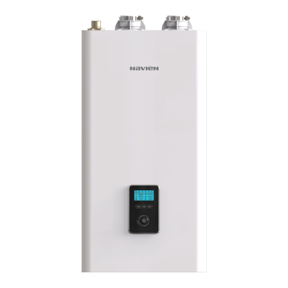
- Page 10 General Specifications Item NFC-175 NFC-200 Dimensions 17.3 in (W) x 17.3 in (D) x 33.5 in (H) Boiler Weight 145 lb (66 kg) Boiler Weight with Water 183 lb (83 kg) Installation Type Indoor Wall-Hung Venting Type Forced Draft Direct Vent...
-
Page 11: Components
1.4 Components The following diagram shows the key components of the boiler. Component assembly diagrams and particular parts lists are included in the Appendixes. Intake Air Exhaust PRV-Air Vent Connection Mixing Chamber Fan & Motor Assembly Igniter Flame Rod Dual Venturi Igniter Transformer Fire-Tube Type Heat Exchanger... - Page 12 Intake Air Filter Mixing Chamber Fan & Motor Assembly Dual Venturi Igniter Flame Rod Igniter Transformer Gas Valve Fire-Tube Type Heat Exchanger Air Intake Pipe Gas Pipe ASME Name Plate Front Panel Terminal Block Circulation Pump Power Switch Mixing Valve Water Adjust Valve DHW Exchanger 3-Way Valve...
-
Page 13: Dimensions
1.5 Dimensions The following diagrams show the dimensions of the boiler and the table lists the supply connections. Supply Connections Description Diameter Air Intake 2 in Exhaust Gas Vent 2 in PRV-Air Vent Connection Heating Supply 1 in Heating Return 1 in Gas Connection Condensate Outlet... -
Page 14: Rating Plate
1.6 Rating Plate The Navien NFC boilers come from the factory configured for use with Natural Gas (NG). Before starting the installation, check the rating plate located on the side of the boiler to ensure that the boiler matches the gas type, gas pressure, water pressure, and electrical supply available in the installation location. -
Page 15: Installing The Boiler
2. Installing the Boiler 2.1 Removing the Wood Pallet from the 2. Remove the accessory box, the wood pallet, the upper container, and the lower pad. boiler After you open the box, remove the wood pallet and the pallet brackets and then install the boiler. Accessory CAUTION After opening the box, verify that all included accessories are... -
Page 16: Choosing An Installation Location
2.2 Choosing an Installation Location 4. Remove the two pallet brackets. When choosing an installation location, you must ensure that the location provides adequate clearance for the boiler, adequate venting and drainage options, and sufficient access to gas, water, and electrical supplies. Carefully consider the following factors when choosing an installation location: Compliance Requirements Local, state, provincial, and national codes, laws, regulations, and... - Page 17 Do not install the boiler on carpeting. Navien will not be responsible for water damages that occur as a result. For more information about condensate drainage, refer to “3.3 Connecting the Condensate Drain”...
-
Page 18: Mounting The Boiler To The Wall
Switches” on page 60 for the appropriate altitude setting. 2.3 Mounting the Boiler to the Wall Navien NFC boilers come with an upper mounting bracket that is pre-drilled at 16 in (400 mm) on center for easy installation on standard wall studs. If the strength of the wall is insufficient or if the framing is non-standard or uneven, reinforce the area before installing the boiler. -
Page 19: Installing The System Piping
All systems, old and new, system. Freeze protection for new or existing systems requires must be cleaned to remove flux, grease and carbon residue. Navien specially formulated glycol, which contains inhibitors to prevent recommends cleaning the boiler system with cleaning products the glycol from attacking the metallic system components. - Page 20 (oxygen) and other impurities. To avoid the presence of oxygen, ensure all of the air is removed from The Navien NFC boiler comes with an air vent and an adapter the system during commissioning via strategically placed and bushing that must be connected to the air vent connection.
- Page 21 Refer to the expansion tank manufacturer’s Internal LWCO instructions for additional details. The Navien NFC boiler is equipped with a factory-installed, Follow the guidelines below when installing an expansion tank. pressure-sensing type low water cutoff (LWCO) appliance. The minimum operation pressure for this appliance is 6 psi by default.
- Page 22 Air Vent Pressure Relief Valve WARNING External LWCO Installing the pressure relief valve improperly may result ● in property damage, personal injury, or death. Follow all instructions and guidelines when installing the pressure relief valve. The valve should be installed only by a licensed professional.
-
Page 23: Installing A Domestic Hot Water (Dhw) System
3.2.1 Guidelines for the DHW System flow. The Navien manifold system allows for easy separation of the With its multi-purpose design, the Navien NFC boiler provides hot Boiler-Primary loop from the System-Secondary loop(s). Refer to water on demand. - Page 24 150 psi pressure relief valve on the hot water outlet. The Navien NFC boiler has a built-in high When installing pressure relief valve, follow these guidelines: temperature shut off switch, so install a “pressure only“ relief valve.
-
Page 25: Connecting The Condensate Drain
3.2.3 DHW System Piping 3.3 Connecting the Condensate Drain The Navien NFC boiler creates condensation when it operates. This condensation has an acidic pH of 3-5. Follow all local codes CAUTION and regulations when disposing of condensate from the boiler. - Page 26 3. Attach the clip to the condensate trap. Before connecting the condensate drain, choose one of the following disposal options: 4. Ensure that the condensate trap is firmly fixed to the bottom of the boiler. a. From the boiler directly into an external drain. Do not install a fixed connection for the drain.
- Page 27 To connect the condensate drain: If option 'b' (p. 25) is selected as the disposal option, the Navien condensate neutralizer kit is recommended. The condensate from 1. Connect a drain line to the in fitting at the bottom of the the appliance flows through the neutralizing media and increases boiler.
-
Page 28: Filling The System
6.0. For replacement media, contact your local Navien distributor. 3.4 Filling the System Before filling the boiler, loosen the air vent cap to enable the Y-fitting system to fill properly. -
Page 29: Testing The Water System
3.4.1 Built-in Water Fill Connection 3.5 Testing the Water System The Navien NFC boiler is equipped with an auto-feeding water connection and motorized feeding valve. Therefore, installation WARNING of additional system water fill connection is not necessary in most cases. See the following figure for an example of a water fill Ensure that the boiler is full of water before firing the burner. -
Page 30: Considerations For System Applications
Read and follow the guidelines listed below when installing system 3. Fill the boiler to the correct system pressure. The correct piping for the Navien NFC boiler: pressure will vary with each application. The typical cold water System application drawings are intended to explain the system fill pressure for a residential system is 12 psi. - Page 31 3.6.1 Temperature Control Device Applications Air Handler Interface The Navien NFC boiler can control the operation of an air handler NFC series boilers come with water adjustment valves and mixing when a thermostat is used in combination with the air handling valves included as to ensure a stable supply of hot water without unit.
- Page 32 3.6.3 System Application - Zone System with Pumps (Primary/Secondary Piping) Additional Zone Zone #2 Zone #1 NaviClean Air Separator Not to exceed 4 pipe Dia or Max. 12" Pressure Air Vent Relief Valve Backflow preventer Pressure reducing valve Expansion Tank Make-up Water System application drawings are intended to explain the system piping concept only.
- Page 33 3.6.4 System Application - Air Handler System Pressure Relief Valve Air Vent NaviClean Air Separator Make-up Water Backflow preventer Expansion Tank Pressure reducing valve Air Flow Air Handler System application drawings are intended to explain the system piping concept only. Note ●...
- Page 34 3.6.5 System Application - Combi Pre-Heat Mode Combi pre-heat allows NFC boilers to pre-heat to ensure a quick supply of hot water when there is no external recirculation system. This mode is enabled by default. (Refer to the combi pre-heat section in "11.3.4 Setting the DHW Operation" on page 90 for details.) 3.6.6 System Application - External Recirculation with NaviCirc The following pump models are recommended for use with the NFC boiler and DHW recirculation systems.
- Page 35 3.6.7 System Application - External Recirculation with HotButton and NaviCirc External Recirculation Mode For best performance, select the manual option in the External recirculation DHW recirculation mode. Combi pre-heat is the default mode for DHW recirculation. To select external recirculation, refer to the combi pre-heat and external Note recirculation sections in "11.3.4 Setting the DHW Operation"...
- Page 36 3.6.8 External Recirculation with Dedicated Return Line (Always On, Weekly, Intelligent) External Recirculation Mode For best performance, select the intelligent or weekly option in the external recirculation DHW recirculation menu. Combi pre-heat is the default mode for DHW recirculation. To select external recirculation, refer to the combi pre-heat and external Note recirculation sections in "11.3.4 Setting the DHW Operation"...
- Page 37 3.6.9 External Recirculation with HotButton and Dedicated Return Line (HotButton, Aquastat) External Recirculation Mode To use the aquastat mode, install an aquastat to the DHW pipe lline and connnect to the CNC6 terminal on the PCB. (Refer to "3.7.4 Wiring Diagram - Zone Pump System with DHW Recirculation"...
-
Page 38: Examples Of Electrical Connections
3.7 Examples of Electrical Connections WARNING Improperly connecting the electrical supplies can result in electrical shock and electrocution. Follow all applicable electrical codes of the local authority having jurisdiction. Connecting the electrical components should be performed only by a licensed professional. CAUTION Label all wires before disconnecting them when you work on the controls. - Page 39 3.7.3 Wiring Diagram - Zone Pump System NFC boilers can operate a heating system with up to 3 zones. The following is the wiring diagram for a zone pump system with 3 zones. Without 24VAC Connections LWCO AC24VL AC24VN lLWCO AC24VL AC24VN lLWCO...
- Page 40 With 24VAC Connections LWCO AC24VL AC24VN lLWCO AC24VL AC24VN lLWCO AC24VL AC24VN 24 VAC N Thermostat Input SUPPLY RETURN OUTDOOR T/S_ZONE3 24 VAC L Zone pump 1 TEMPERATURE SENSOR (max. 2.5 A) Thermostat 1 24 VAC N Thermostat Input 24 VAC L SUPPLY RETURN OUTDOOR...
- Page 41 3.7.4 Wiring Diagram - Zone Pump System with DHW Recirculation NFC boilers can use both the 3 zone heating system and the DHW recirculation feature. The following wiring diagram shows the 3 zone system and the DHW external recirculation feature. Without 24VAC Connections LWCO AC24VL...
- Page 42 With 24VAC Connections LWCO AC24VL AC24VN lLWCO AC24VL AC24VN Recirculation pump (max. 2.5 A) Recirculation Timer, Aquastat, or HotButton lLWCO AC24VL AC24VN 24 VAC N Thermostat Input SUPPLY RETURN OUTDOOR T/S_ZONE3 24 VAC L Zone pump 1 TEMPERATURE SENSOR (max. 2.5 A) Thermostat 1 24 VAC N Thermostat Input...
- Page 43 3.7.5 Wiring Diagram - the Navien SmartZone + The Navien Smart Zone + controller may be used with NFC boilers to operate a heating system with more than 3 zones. When Navien boilers are used with a Navien Smartzone+ zone pump controller, an RS-485 data communication link is established through the Ready-link connection.
- Page 44 3.7.6 Wiring Diagram - Generic Zone System with 3.7.7 Wiring Diagram - Generic Zone System with Zone Valves Zone Pumps <NFC> <NFC> lLWCO lLWCO AC24VL AC24VL AC24VN AC24VN SUPPLY RETURN OUTDOOR T/S_ZONE3 SUPPLY RETURN OUTDOOR T/S_ZONE3 TEMPERATURE SENSOR TEMPERATURE SENSOR SUPPLY RETURN OUTDOOR...
- Page 45 3.7.8 Wiring Diagram - Air Handler <NFC> lLWCO AC24VL AC24VN lLWCO AC24VL AC24VN SUPPLY RETURN OUTDOOR T/S_ZONE3 SUPPLY RETURN OUTDOOR T/S_ZONE3 TEMPERATURE SENSOR TEMPERATURE SENSOR <Air Handler> Connect the pump wires to the system pump. <NFC> lLWCO AC24VL AC24VN SUPPLY RETURN OUTDOOR T/S_ZONE3...
- Page 46 > 4. SH Control Method to select one of the control modes. For best performance, wrap the sensor and pipe section with thermal insulation. ● A single temperature sensor is supplied with the boiler. Additional temperature sensors are available for purchase. Contact ● Navien for more information. About the Boiler...
-
Page 47: Connecting The Gas Supply
This boiler cannot be converted from natural gas to propane ● or vice versa without a Navien gas conversion kit. Do not 5. Install certified full port valves on the gas supply line and attempt a field conversion of this boiler without a Navien gas boiler. - Page 48 BTUs. Also, ensure that the flexible line has no crimps or tight bends in it, as this will restrict gas flow. When using rigid pipe, Navien recommends the ● installation of a union on the gas supply line close to the boiler, to facilitate any future maintenance or service.
-
Page 49: Gas Pipe Sizing Tables
4.1 Gas Pipe Sizing Tables The following tables are referenced from the 2012 National Fuel Gas Code and are for reference only. Please consult the gas pipe manufacturer for actual pipe capacities. Maximum Natural Gas Delivery Capacity In Cubic Feet (ft ) per Hour (0.60 Specific Gravity;... -
Page 50: Measuring The Inlet Gas Pressure
Maximum Liquefied Propane Delivery Capacity In Thousands of BTU/H (0.5 in WC pressure drop) Length (including fittings) Pipe Size 10 ft 20 ft 30 ft 40 ft 50 ft 60 ft 80 ft 100 ft 125 ft 150 ft 175 ft 200 ft 250 ft (3 m) - Page 51 To measure the inlet gas pressure: 8. Unfasten the 4 latches (2 at the top and 2 at the bottom) to remove the front cover and gain access to the internal 1. Shut off the manual gas valve on the gas supply line. components.
-
Page 52: Venting The Boiler
5. Venting the Boiler 2. Insert the pipe into the vent collar to start the vent run. Make sure to completely slide the vent into the collar until the end WARNING makes contact with the bottom of the socket. Improper venting of the boiler can result in excessive levels of Verify that 1- ”... -
Page 53: Selecting A Vent Type
If you use a corrugated material, ensure that there is not inadvertent Navien also recommends installing a new vent system with this crimping of, or damage to, the intake air pipe. - Page 54 Vent Pipe 2" problem, any freezing damage which occurs from back drafting will not be covered by the Navien warranty. If there is any question about the possibility of back drafting in the installation location, use a direct venting system for the boiler.
- Page 55 Canadian Non-Direct Vent US Non-Direct Vent Description Installations Installations Clearance above grade, veranda, porch, deck, or balcony 12 in (30 cm) 12 in (30 cm) 48 in (120 cm) below or to side Clearance to window or door that may be opened 36 in (91 cm) of opening;...
-
Page 56: Selecting Vent Pipe Materials
5.2 Selecting Vent Pipe Materials CAUTION Venting requirements differ in the US and Canada. Consult the following chart or the most recent edition of ANSI Z223.1/NFPA This boiler has a built-in control to limit the exhaust ● 54 or CAN/CGA B149.1, as well as all applicable local codes and temperature to 149°F (65°C). -
Page 57: Measuring Vent Length
5.3 Measuring Vent Length IPEX Low Profile Termination Kit: ● 2 in Low Profile Vent Kit #196984 3 in Low Profile Vent Kit #193985 The maximum vent length when using 2 in exhaust ducts is 60 ft (18 m). The maximum vent length when using 3 in vent ducts The following polypropylene vent terminations are approved for is 150 ft (45 m). - Page 58 Indoor Boiler Installation Venting Examples Non-Concentric Sidewall Venting - Air is drawn from a different ● location that is at least 12 in (300 mm) away from the exhaust The following are some possible indoor venting options: termination. The exhaust termination can be located either on the sidewall or roof.
- Page 59 Flexible PP Exterior View Model Type Vent Dia. Centrotherm Innoflue Flex NFC-175/200 2 in 50 ft * IPEX and Centrotherm Low Profile terminations only Only the flexible vent models listed above are approved for use ●...
-
Page 60: Setting The Dip Switches
5 & 6 Country US/Canada 6-OFF 1-stage MAX 1-ON, 2-ON Space Used 7-OFF 3 & 4 Reserved Heating Unused 7-ON Thermostat NFC-200 5-OFF, 6-OFF 5 & 6 Model Exhaust Used 8-OFF NFC-175 5-ON, 6-OFF Temperature Unused 8-ON Control Setting the DIP Switches... - Page 61 When PCB DIP switch 2 #8 is set to On, ensure that Note ● CPVC, polypropylene, or stainless steel is used for exhaust venting. This unit may be installed at elevations up to 10,100 ● ft (3,078 m) for use with natural gas and propane. To use the unit at a specific altitude, the DIP switches should be set as described above.
-
Page 62: Connecting The Power Supply
Do not connect the boiler to a 220-240V AC power supply. Doing ● so will damage the boiler and void the warranty. All the Navien NFC boilers are supplied with a factory-installed, ● 3-pronged (grounded) plug. The boiler’s current rating is 12 A and can be plugged into any grounded electrical outlet adjacent to the boiler. -
Page 63: Installing A Cascade System
The setup you choose will vary based on the installation location, local building codes, and other factors. Follow all applicable regulations when installing a cascade system. You can connect up to 1 combi-boiler and 15 Navien water heaters (NPE model) to meet high-volume heating demands. Some possible connection options include the following:... - Page 64 These specifications may vary depending on installation conditions. Piping Sizes for an NFC Boiler with up to 15 NPE Water Heaters Model ΔT=54°F Flow rate (GPM) Water Velocity (ft/s) Pipe Diameter (mm/in) NFC-175/200 NPE-240 14.38 5.61 1 in. 21.57 5.54...
-
Page 65: Cascade System - Recirculation System Application Example
8.2 Cascade System - Recirculation System Application Example When using the cascade system, external recirculation can only be connected to and controlled by the NPE “A” water heater. Set each individual water heater to the appropriate recirculation mode utilizing the 2-way valve and front panel DIP switches. Refer to the NPE Installation Manual for additional details. - Page 66 If Recirculation Return Line Is Not Installed Install a NaviCirc valve at the furthest fixture from the water heaters and connect a by-pass line on the 1st NPE “A” unit as illustrated below. Refer to the NaviCirc and NPE Installation Manuals for additional details. The NFC boiler should be set to Combi Pre-heat Mode. Pressure Relief Valve Air Vent...
-
Page 67: Connecting The Communication Cables
8.3.1 Connecting the Communication After connecting the Ready-Link communication cables, restore You can connect one NFC boiler with up to 15 Navien water power to the boiler and turn on all boilers using the Power button. heaters (NPE Model), using the Ready-Link communication cables. - Page 68 3. On the sub NPE water heater panel, press and hold the Diagnostic and Down(-) buttons for more than 2 seconds. “SL.01” will appear on the display to confirm that this water heater is set as a sub. 4. Repeat step 2 to configure the rest of the sub NPE water heaters in the system.
-
Page 69: Installing A Common Vent System
To ensure the safe and correct installation of the common vent system, carefully follow the instructions and guidelines. Check to see if all contents are included in the package (refer to The Navien Common Vent System* provides an easy way to install ● the “Included Items” on page 74). - Page 70 Adequate Installation Clearances CAUTION It is necessary to leave clearance for service access. CAUTION Do not install the boiler on carpeting. Clean, Debris and Chemical-free Combustion Air Do not install the boiler in areas where dust and debris may Install the boiler in an area that allows for service and maintenance ●...
- Page 71 General and Local Standards Information Cutting and Assembling Common Vent System Components When installing and operating the common vent system, the following standards and regulations must be complied with and Standard tools are suitable for the cutting and assembly of adhered to: common vent system components.
- Page 72 Vent Pipe Pitch and Supports Use approved solvent type cement for the proper Note ● vent materials. For horizontal runs, slope the horizontal section upward toward Use solvent type cement only. ● the vent termination at a rate of ” per foot (2% slope). Check the date of manufacture before using the ●...
- Page 73 1 combi-boiler (NFC Follow the instructions listed below to determine the length of a Model) and 7 Navien water heaters (NPE Model). common vent. 1. Add the BTU/H input ratings for each unit in the cascading system to determine the total BTU/H rating.
-
Page 74: Navien Backflow Damper (Back-Draft Damper)
9.2 Navien Backflow Damper (Back-draft Maintenance Port Damper) Navien Backflow Damper has a maintenance port to allow you to easily inspect the operating condition of the damper plate. The Navien backflow damper prevents backflow (back-draft) at the exhaust vent while the boiler unit operates. -
Page 75: Starting The Common Vent System
9.3 Starting the Common Vent System 3. Connect the backflow damper to the exhaust duct of the boiler unit. 9.3.1 Backflow Damper Assembly Follow the instructions below to assemble the backflow damper on the NFC boiler unit: 1. Remove the screws from the exhaust vent adapter. 4. - Page 76 9.3.2 Connecting the Pipe to the Damper The length of vent pipe from the unit to the common Note vent main trunk pipe must not exceed 20’ of equivalent length. 1. Measure 1- ” from the end of the vent pipe, then draw a mark at that distance.
-
Page 77: Connecting And Terminating The Vent Pipe
9.4 Connecting and Terminating the Vent Pipe Refer to the following example to install the common vent system. The installation area should be measured to ensure that sufficient space is available to install the boiler units and the common vent system. Ensure that the common vent system is installed near the boiler units while satisfying all clearance requirements that are specified in this manual as well as the Installation Manuals supplied with the boiler units. -
Page 78: Setting Up The Common Vent System
9.5 Setting Up the Common Vent System 9.6 Common Vent Termination Clearances Refer to the following figures when setting the common vent type. 9.6.1 Direct Vent Application – Vertical To view and configure the cascade settings, press the Back button ) and the Menu button ( ) simultaneously for 3 seconds, and Installation... - Page 79 9.6.3 Direct Vent Application – Horizontal The illustration is intended for reference purposes Note ● only. Installation Direct the exhaust away from any building ● openings. During cold weather situations, the temperature of ● i n . m ) m the exhaust will be much warmer than the ambient 0 0 m 1 2 "...
-
Page 80: Installing A Condensate Drain
9.7 Installing a Condensate Drain To install a condensate drain to the cascade system: 1. Form a loop with a drain hose and fix it with a tie. Refer to the following examples to install a condensate drain hose (field supplied) to the common vent system. The condensate While shaping the hose, do not bend the hose Note ●... -
Page 81: Exhaust Vent Termination Clearances (For Direct Vent)
9.8 Exhaust Vent Termination Clearances (For Direct Vent) Description Canadian Direct Vent Installations1 U.S. Direct Vent Installations2 Clearance above grade, veranda, porch, deck, or 12 in (30 cm) 12 in (30 cm) balcony Clearance to window or door that may be opened 12 in (30 cm) 12 in (30 cm) Clearance to permanently closed window... -
Page 82: Maintenance
9.9 Maintenance 3. Reinstall the gasket and maintenance port cover, and then fix them with a set screw. Periodically check the damper condition inside the backflow damper through the maintenance port to ensure optimal performance of the system. Follow the instructions to check the damper condition and replace the backflow damper if necessary. -
Page 83: Installation Checklist
To troubleshoot any operational problems refer to “Troubleshooting” in the Owner’s Manual. If you have additional questions or need assistance with installation, contact Technical Support at 1-800-519-8794 or 1-949-420-0420, or refer to the technical support section of Navien’s website (www.navien.com). Installing the boiler... - Page 84 Connecting the Space Heating Piping Has the system been filled (less than 80 psi) and purged of air? Does the piping incorporate means for air removal (scoop, separator, etc.)? Is there an expansion tank installed and set to the proper system pressure? If antifreeze has been used, is it the proper type and is the concentration appropriate? If an external low water cut off (LWCO) is installed, is it wired to the boiler? Connecting a Pressure Relief Valve...
- Page 85 Connecting the Power Supply Is the supplied voltage 110-120V AC? Is the boiler plugged into a properly grounded outlet? If you have made a direct power supply connection, have you installed a power switch to facilitate end-user maintenance? Have you checked the polarity of the electrical connection? PCB DIP switch setting (DIP SW 2, set of 8) Gas type: Is switch #1 set correctly for LP (ON) or NG (OFF)? If continuous boiler operation is required, is switch #7 in the up (ON) position?
-
Page 86: Operating The Boiler
11. Operating the Boiler 11.1 Turning the Boiler On or Off 2. Press the Command dial ( ) to select the space heating temperature. The highlighted section will flash. To turn the boiler on or off, press the Power button for 0.3 seconds. 3. - Page 87 11.2.2 Adjusting the DHW Temperature 6. Press the Back button ( ) to return to normal operation mode, or rotate the Command dial ( ) to adjust other To adjust the water temperature: operation conditions. You can adjust the temperature while the display is flashing. Once 1.
-
Page 88: Accessing Basic Menu Items
11.3 Accessing Basic Menu Items 11.3.2 Viewing Basic Information To view information about the boiler, press the Menu button ( In the Main Menu screen, you can view the boiler’s operating and then select “2. Status Information”. conditions, configure the space heating and DHW temperatures, and review error history. - Page 89 11.3.3 Setting the Space Heating Operation Item Description 17. Fan Target RPM Set fan speed (RPM) To set the boiler’s space heating operation, press the Menu button ), and then select “3. Space Htg Operation”. 18. Fan Current RPM Fan speed (RPM) 19.
- Page 90 The Outdoor Reset mode Default: 0 min ● cannot be used when using the DHW mode. Enable or disable heating zones utilizing the Navien Zone Controller. 3. Navien zone cont. Setting range: Enabled/Disabled 11.3.4 Setting the DHW Operation ●...
- Page 91 Combi Pre-Heat Press the Back button ( ) to return to the previous screen or menu. Item Description When using the combi pre-heat feature, you can choose commands in the menu to preheat according to the set DHW Set the hot water temperature(°F). temperature.
- Page 92 External Recirculation When Installing the Cascade System When using the External Recirculation feature, you can choose When using the recirculation feature in the cascade system , you commands in the menu to preheat according to the set DHW can choose commands in the menu to preheat according to the temperature.
- Page 93 11.3.5 Viewing Error History 11.3.6 Viewing Other System Information To view the error history, press the Menu button ( ), and then To view the miscellaneous system information, press the Menu select “5. Error History”. button ( ), and then select “6. EMS Data”. A list of 10 recent errors are displayed on the screen, with the most Rotate the Command dial ( ) to switch between the information...
-
Page 94: Accessing Advanced Menu Items
11.4 Accessing Advanced Menu Items 11.3.7 Setting the Display Options To set the front panel display options, press the Menu button ( and then select “7. Configuration”. 11.4.1 Viewing Service Information To view service information about the boiler, press the Back button ) and the Menu button ( ) simultaneously for 3 seconds, and then select “1.Service Status Info”. - Page 95 11.4.2 Viewing Input and Output Status Item Description To view the boiler’s input and output status, press the Back button 14. LWCO Input LWCO input status ) and the Menu button ( ) simultaneously for 3 seconds, and Status then select “2. Input/Output Status”. 15.
- Page 96 After entering the parameter setting screen, rotate the Command Item Description dial ( ) to switch between the parameters or to increase/ decrease setting values. Press the Command dial ( ) to select a Set space heating maximum heat parameter or to confirm after making changes. capacity limit.
- Page 97 If you enter an incorrect password 10 times or no Note ● Item Description input from the front panel display for 5 minutes, the Set the space heating pump over-run boiler will return to Normal mode. time. 17. Boiler Pump To return to the previous mode, press the Reset ●...
- Page 98 Press the Back button ( ) to return to the previous screen or Item Description menu. View the operating status of individual 6. Cascade Info. units in the cascade system. Item Description Set the type of ventilation. To enter the Cascade Main setting ●...
- Page 99 11.4.6 Diagnosing the Boiler System Item Description To run a series of test procedures for a system diagnosis, press the Test the zone 2 pump operation. Back button ( ) and the Menu button ( ) simultaneously for 3 The zone 2 pump is turned on as ●...
- Page 100 11.4.7 Setting the Special Operation Modes 11.4.8 Operating in Air Purge Mode To operate the boiler in special operation modes, press the Back To operate the boiler in air purge mode, press the Back button button ( ) and the Menu button ( ) simultaneously for ) and the Menu button ( ) simultaneously for 3 seconds, and...
-
Page 101: Understanding Error Codes
11.5 Understanding Error Codes When an error code appears on the front panel, refer to the following chart for a definition and possible remedy for the situation. Error Code Reason Self-Diagnostic/ Action E001 Heatexchanger over temperature Reset the boiler from the front panel. E003 Ignition failure Ensure that the main gas supply valve is open. - Page 102 Error Code Reason Self-Diagnostic/ Action E615 Abnormal operation: input and memory Contact technical support at 1-800-519-8794. E736 Abnormal operation: cascade communication Contact technical support at 1-800-519-8794. Abnormal operation: outdoor temperature sensor Ensure that the outdoor reset curve is configured properly. ●...
-
Page 103: Appendixes
Table 1. Orifice Size WARNING This conversion kit must be installed by a qualified service agency* in accordance with Navien’s instructions and all WARNING applicable codes and requirements of the authority having jurisdiction. The information in these instructions must be Be careful not to confuse the LP CONVERSION KIT and HIGH ●... - Page 104 Procedure: 4. With the internal components exposed, locate the gas inlet pipe and the gas valve, as shown in Figure 2. The procedure below can be applied to both LP Note conversion and High Altitude conversion. Distinguish the kit supplied with the boiler before installing. 1.
- Page 105 Attempting to alter or measure the gas valve outlet pressure ● could result in damage to the valve, causing potential severe personal injury, death or substantial property damage. Navien NFC boilers are shipped ready to fire natural gas ONLY. Figure 5. Exploded View of Gas Pipe Assembly Appendixes...
- Page 106 8. Remove the Gas Orifice, ensure that the packing is properly This unit may be installed at elevations up to 10,100 ft Note ● seated inside the port, and then install the new Gas Orifice for (3,078 m) for use with natural gas and propane. use with LP gas.
- Page 107 1-stage MIN 1-OFF, 2-ON 1-stage MAX 1-ON, 2-ON Figure 6. Insert the Analyzer 3 & 4 Reserved NFC-200 5-OFF, 6-OFF 5 & 6 Model NFC-175 5-ON, 6-OFF High fire Low fire Model Altitude Fuel 0-5,399 ft 10.2 10.8 NFC-175 NFC-200 5,400-10,100 ft 10.2...
- Page 108 Model Altitude Kit Part No. Gas Type Offset 0-5,399 ft NAC-N200 -0.04 in ±0.01 in NFC-175 5,400-10,100 ft NAC-NCH200 Figure 7. Set Screw Location NFC-200 -0.02 in 0-10,100 ft NAC-LC200 ±0.01 in The set screw is located behind the screw-on Note cover.
- Page 109 c. Activate multiple zones and set the boiler to operate at 13. Once the CO or offset values have been confirmed, apply the 1-stage MIN mode (refer to “11.4.7 Setting the Special included conversion stickers to show that the appliance has Operation Modes”...
-
Page 110: Wiring Diagram
12.2 Wiring Diagram Main GV1 Main GV2 THERMOSTAT3 T/S1 Outdoor Temperature Sensor Flow Sensor OUTDOOR System Return Temperature Sensor RETURN AWS_Valve System Supply Temperature Sensor SUPPLY 110 Appendixes... -
Page 111: Ladder Diagram
12.3 Ladder Diagram AC INPUT(AC 120VAC) NEUTRAL Terminal Board Relay 1 R/C Pump Relay 2 Boiler Pump Relay 3 Zone1 Pump Relay 4 Zone2 Pump Relay 5 Zone3 Pump FILTER Dual Venturi Relay 5 Relay 6 Igniter 3WAY VALVE Relay 7 Primary Primary SMPS... -
Page 112: Outdoor Temperature Sensor
Make sure wiring connections are secure before closing the cap. ● The sensor is a water resistant appliance. ● Any damage to the appliance may require the replacement of ● the entire component. Navien Outdoor Temperature Sensor Kit 112 Appendixes... -
Page 113: Outdoor Reset Control
12.5 Outdoor Reset Control Outdoor Temperature Sensor Installation Guidelines The Outdoor Reset Control feature may be used to enhance energy Supply Set Point Return Set Point efficiency while maintaining optimal heating performance. With Heat Load Range Range the Outdoor Reset Control, the space heating temperature setting automatically changes according to the outdoor temperature and Finned Tube 120-180°F... -
Page 114: Component Assembly Diagrams And Parts Lists
12.6 Component Assembly Diagrams and Parts Lists 12.6.1 Case Assembly 114 Appendixes... - Page 115 Description Part # Remark Case Upper 20041092A Case Middle 20044456A Case Lower 20044457A Base Bracket 20007609A Base Lower Bracket 20007643B Heat Exchanger Bracket 20040243A Screw (M4X10L) 20038757A Main PCB 30021486A Terminal PCB 30021496A Intake Air Duct Assembly 30008662B Intake Air Filter 30016248B Base Packing 20041078A...
- Page 116 12.6.2 Heat Exchanger and Waterway Assembly 116 Appendixes...
- Page 117 Description Part # Remark Heat Exchanger Assembly 30019155A NFC-175/200 Drain Pan Assembly 30021887A Fastener 20040255A Heat Exchanger Drain Cap 20042237A Drain Pan Packing 20040241A O-ring (P26) 20032409A Drain Pan Adapter 20044473A Screw (M4X10L) 20038753A Exhaust Duct (Lower) 20040242A Exhaust Duct (Upper)
- Page 118 12.6.3 Combustion Parts Assembly 118 Appendixes...
- Page 119 30017402A NFC-175/200 Intake Pipe 30019120A Orifice Packing 20022660A 20041039A NFC-175/200 (NG) Gas Orifice 20041040A NFC-175/200 (LP) 20045082A NFC-175/200 High Altitude (NG) O-Ring (P34) 20019090A Gas Connector (Upper) 20042238A O-Ring (P20) 20006934A Gas Connector Adapter 20042239A Gas Valve 30011586B Gas Pipe...
- Page 120 12.6.4 Waterway Assembly Description Part # Remark Plate Heat Exchanger 30021098A DHW Connection Adapter 30021869A Mixing Valve Adapter 20044471A Flow Adjust Valve 30008247A DHW Inlet Connection Adapter 20044470A DHW Temperature Sensor (Blue) 30022207A DHW Inlet Connection Adapter 20044477A Circulation Pump Inlet Adapter 30021865A Heating Return Adapter 20044488A...
- Page 121 Description Part # Remark Fastener (19.7) 20007733B O-Ring (P14) 20011438A O-Ring (P16) 20017210A O-Ring (P18) 20006947A Heating Return Adapter Filter 30014682A O-Ring (P25) 20032528A 20017744A DHW Temperature Sensor (Red) 30015178A 3-Way Valve Body 30022588A Mixing Adjust Valve 30011532A DHW Outlet Adapter 20044487A Heating Supply Adapter 20044489A...
- Page 122 Memo...
- Page 123 Memo...
- Page 124 Installation & Operation Manual NFC Condensing Combi-Boilers Getting Service If your boiler requires service, you have several options for getting service: Contact Technical Support at 1-800-519-8794 or on the website: www.navien.com. ● For warranty service, always contact Technical Support first. ●...
Need help?
Do you have a question about the NFC-175 and is the answer not in the manual?
Questions and answers