Table of Contents
Advertisement
Quick Links
GTC-700
Instruction Manual
Headquarters / Engineering research laboratory :
23 Gunpo Advance d Industry 1-ro(Bugok-dong), Gunpo-si, Gyeonggi-do
Tel +82-31-490-0800 Fax +82-31-490-0801
Yeongnam business office / Plant :
55 Gonghangap-gil 85beon-gil, Gangseogu, Busan Metropolitan City
Tel +51-973-8518 Fax +51-973-8519
E-mail : info@gastron.com
www.gastron.com
Read in detail for correct use.
Advertisement
Table of Contents

Related Manuals for GASTRON GTC-700


Summary of Contents for GASTRON GTC-700
- Page 1 Headquarters / Engineering research laboratory : 23 Gunpo Advance d Industry 1-ro(Bugok-dong), Gunpo-si, Gyeonggi-do Tel +82-31-490-0800 Fax +82-31-490-0801 Yeongnam business office / Plant : 55 Gonghangap-gil 85beon-gil, Gangseogu, Busan Metropolitan City Tel +51-973-8518 Fax +51-973-8519 E-mail : info@gastron.com www.gastron.com Read in detail for correct use.
- Page 2 Gas & Flame Thank you very much for purchasing a product from Gastron Co. Ltd. Our Gastron Co.Ltd. is a company specialized in Gas Detector & Gas Monitoring System and have been Detection System recognized by many customers for the best quality and use convenience. We always seek to help our customers to find the product they need and we continuously research to develop gas detectors that satisfies our customers.
-
Page 3: Table Of Contents
GTC-700 Contents Contents www.gastron.com Instruction Manual 04_05 1. Overview ······································································································································································ 7. Interface ······································································································································································· 7.1. RS485 MODBUS Interface ····································································································································· 2. Characteristics ····························································································································································· 7.1.1. Network Setting ····································································································································· 7.1.2. RS485 MODBUS Register(Used Commonly with MODBUS TCP/IP) ····················································· 3. Specifications ······························································································································································· 3.1. Basic Specification (Based on 128 Channel) ·····································································································... -
Page 4: Overview
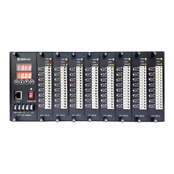
Nominal: Input Voltage Absolute max: GTC-700 Series is built with FND digital display (mA value) and LED that displays status of analog input channel, Ripple maximum allowed: 1V pk-pk operation status of internal network, and power on status for the main power. It has RS-485 port and Ethernet port for... -
Page 5: Name And Description Of Each Part
External 0 ~ 20 mA current signal '-' Input terminal Terminal Analog Input Terminal Press to remove analog input terminal Unlock Button [Table 1. Power Configuration Description] [Figure 1. GTC-700 External Components] NAME DESCRIPTIONS Mount hole Mount hole for fixing the product Common Unit holder It is used for detachment or fixing of Common unit. -
Page 6: Internal Components
GTC-700 4. Name and Description of Each Part 5. Installation www.gastron.com Instruction Manual 10_11 4.2. Internal Components ■ It is prohibited for an individual, other than an approved user or a technician responsible for installation and repair from the head office, to install a gas leak detector on site or open the cover of the installed gas leak detector and manipulate it. -
Page 7: Channel Configuration
GTC-700 5. Installation 5. Installation www.gastron.com Instruction Manual 12_13 5.2. Channel Configuration ■ Channel configuration per slot is as shown in the table below. ■ GTC-700 can be configured with 16 slots (possible for max. 128 signal input) and 8 signal inputs of 4-20 mA are SLOT NO CHANNEL NO CHANNEL DISPLAY NO NOTE CH.1-1 possible in each slot. CH.1-2 ■ Configured analog input unit must be set from the left side and it is numbered as slot1 from the left. CH.1-3 CH.1-4 Slot1 CH.1-5 CH.1-6 CH.1-7 CH.1-8 CH.2-1 CH.2-2 CH.2-3 CH.2-4 Slot2 CH.2-5... -
Page 8: Input Signal Configuration
GTC-700 5. Installation 6. Operation Method www.gastron.com Instruction Manual 14_15 5.3. Input Signal Configuration 6.1. Power ON 5.3.1. 3-wire Type Gas detector Connection Method ■ Check wirings for operation power, detection parts, alarm parts, and concentration display. ■ Check the power input then turn ON the power S/W. ■ When the gas detector has 3-wire (V+, mA, V-) for power ■ Check whether power LED at alarm and concentration display parts light on. and 420 mA output components, connect to the Analog as ■ Perform self-test. shown in Figure 5. -
Page 9: Operation Method
GTC-700 6. Operation Method 6. Operation Method www.gastron.com Instruction Manual 16_17 6.2. Measuring Mode 6.3. Operation Setting ■ After power on, when there is no error from "SELF TEST", it automatically enters Measuring Mode. ■ GTC-700 has 6 setting modes as shown below. ■ Each mode can be entered after pressing FUNC key for 2 sec or longer followed by password input. ■ Using UP (▲) or DOWN (▼) key, the user can select a mode then edit it. When there is no key input for 10 sec longer within the same menu, it automatically returns to measuring mode. ■ When RESET key is pressed during mode set-up, it returns to measuring mode. - It displays measurement of channel 1-1 (Channel 1 of Analog Unit 1) - It displays the current 11.58 mA input status of channel 1-1. -
Page 10: Configuration Mode
GTC-700 6. Operation Method 6. Operation Method www.gastron.com Instruction Manual 18_19 6.3.1. Configuration Mode ■ When "FUNC" key is pressed for 2 sec or longer in measuring mode, it enters password input step. - It is password change menu. - The password is for entering device setting menu and pressing UP (▲) or DOWN (▼) key increases or decreases number for password. - Password can be set in a range between '00~99 and default is '00'. -
Page 11: Calibration Mode
GTC-700 6. Operation Method 6. Operation Method www.gastron.com Instruction Manual 20_21 6.3.2. Calibration Mode ■ It is a mode that can calibrate 4-20 mA signal input. - When the calibration is performed normally, the current measurement displays. - It changes the value from current generator and checks whether the output is the same value. -
Page 12: Test Mode
GTC-700 6. Operation Method 6. Operation Method www.gastron.com Instruction Manual 22_23 - Use UP (▲) or DOWN (▼) key to select a channel for setting then press FUNC key to - It is the current test menu. compensate the selected channel. - Pressing FUNC key enables testing from ch. 1-1. - UP (▲) or DOWN (▼) keys can be used to set a value in a range of -1.00 ~ 1.00 in 0.01 unit. When it is set to -1.00, displayed value becomes 19.00 for a measurement of 20.00. -
Page 13: Modbus Tcp/Ip Network Configuration Mode
GTC-700 6. Operation Method 6. Operation Method www.gastron.com Instruction Manual 24_25 6.3.6. MODBUS TCP/IP Network Configuration Mode - It is stop bit setting menu. - Use UP (▲) or DOWN (▼) key to select between 1 or 2. - Pressing FUNC key for 2 sec or longer followed by password input enable menu selection. - Page 14 GTC-700 6. Operation Method 6. Operation Method www.gastron.com Instruction Manual 26_27 - It is the third IP address setting menu. - It is the second subnet mask setting menu. - Use UP (▲) or DOWN (▼) key to select between 0 ~ 255. - Use UP (▲) or DOWN (▼) key to select between 0 ~ 255. - Pressing FUNC key sets the selected address and moves to the next address setting menu.
- Page 15 GTC-700 6. Operation Method 6. Operation Method www.gastron.com Instruction Manual 28_29 - It is the first gateway setting menu. - It is mac address setting menu. - Use UP (▲) or DOWN (▼) key to select between 0 ~ 255. - Pressing FUNC key moves to the menu for checking detailed mac address.
- Page 16 GTC-700 6. Operation Method 6. Operation Method www.gastron.com Instruction Manual 30_31 - It is the fourth mac address setting menu. - There is no change during menu setting. It displays the end of the selected menu. - Use UP (▲) or DOWN (▼) key to select a value between 00 ~ FF (hexadecimal). - After approx. 1 sec, it moves to the initial menu for network setting.
- Page 17 GTC-700 7. Interface 8. Troubleshooting www.gastron.com Instruction Manual 32_33 7.1. RS485 MODBUS Interface MESSAGE VALUE DESCRIPTION & CONDITION RECOVERY Change the failed 7.1.1. Network Setting E-01 0x0001 Analog Input Unit LED driver failure channel card Change the failed ■ Baud rate : 57600 bps( 4800, 9600, 19200, 38400, 57600, 115200 bps ) E-02...
- Page 18 GTC-700 9. Drawings and Dimensions 10. Revision History www.gastron.com Instruction Manual 34_35 VERSION CONTENTS DATE Initial Revision of Manual 2016. 10. 05 [Figure 8. GTC-700 Drawing]...
Need help?
Do you have a question about the GTC-700 and is the answer not in the manual?
Questions and answers