Table of Contents
Advertisement
Quick Links
GTC-200F
Instruction Manual
Headquarters / Engineering research laboratory :
23 Gunpo Advance d Industry 1-ro(Bugok-dong), Gunpo-si, Gyeonggi-do
Tel +82-31-490-0800 Fax +82-31-490-0801
Yeongnam business office / Plant :
55 Gonghangap-gil 85beon-gil, Gangseogu, Busan Metropolitan City
Tel +51-973-8518 Fax +51-973-8519
E-mail : info@gastron.com
www.gastron.com
Read in detail for correct use.
Advertisement
Table of Contents

Related Manuals for GASTRON GTC-200F Series


Summary of Contents for GASTRON GTC-200F Series
- Page 1 Headquarters / Engineering research laboratory : 23 Gunpo Advance d Industry 1-ro(Bugok-dong), Gunpo-si, Gyeonggi-do Tel +82-31-490-0800 Fax +82-31-490-0801 Yeongnam business office / Plant : 55 Gonghangap-gil 85beon-gil, Gangseogu, Busan Metropolitan City Tel +51-973-8518 Fax +51-973-8519 E-mail : info@gastron.com www.gastron.com Read in detail for correct use.
- Page 2 Gas detectors satisfying customers. From now on, solve all anguishes concerning Gas detector with the products of Gastron Co. Ltd, We Gastron Co. will take a responsibility and give you satisfaction. In the present instruction manual, operation method for Gas detector as well as simple methods for maintenance and repair, etc.
-
Page 3: Table Of Contents
GTC-200F Contents Contents www.gastron.com Instruction Manual 04_05 Overview 9. How to operate Channel Unit · · · · · · · · · · · · · · · · · · · · · · · · · · · · · · · · · · · · · · · · · · · · · · · · · · · · · · · · · · · · · · · · · · · · · · · · · · · · · · · · · · · · · · · · · ·... -
Page 4: Overview
24V 1.5A (24V 1.5A) Alarm display Audio signal- Audible(Buzzer) and Visual signal- Visual(LED) GTC-200F Series is protected by a case of DIN Type, and has Wall mount type products with an explosion-proof Alarm clearing Return switch- Manual (Reset switch) case. GTC-200F Series has FND Digital display (PV Value) function and 3-color LED Bar Graphic display (PV and... -
Page 5: Specifications For Channel Card
GTC-200F 4. Specifications for channel card 4. Specifications for channel card www.gastron.com Instruction Manual 08_09 4.1. Common Alarm Unit 4.2. Channel Control Unit ITEMS SPECIFICATION ITEMS SPECIFICATION Input form RS-485 Input form Analog 4-20mA Input measuring period 100ms Measurement display... -
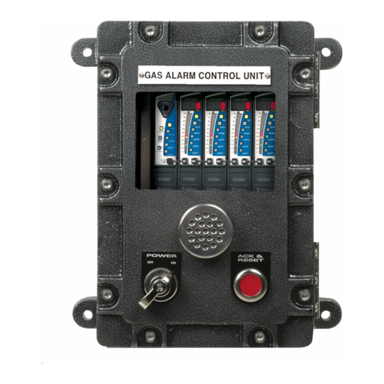
Page 6: Name And Description Of Each Part
GTC-200F 5. Name and description of each part 5. Name and description of each part www.gastron.com Instruction Manual 10_11 5.1. Basic configuration and description NAME DESCRIPTIONS TEMPERED GLASS State of inside can be checked with 10mm of tempered glass. WRENCH BOLT Used for coupling of COVER and BODY. - Page 7 GTC-200F 5. Name and description of each part 5. Name and description of each part www.gastron.com Instruction Manual 12_13 5.3. Configuration and description of alarm unit (Common unit) NAME DESCRIPTIONS Front cover case Front-face Cover for Power Unit Main body case...
-
Page 8: Configuration And Description Of Concentration Display Unit(Channel Unit)
GTC-200F 5. Name and description of each part 5. Name and description of each part www.gastron.com Instruction Manual 14_15 5.4. Configuration and description of concentration display unit (Channel unit) NAME DESCRIPTIONS Alarm 1 LED is lighted upon occurrence of the 1st alarm in each Channel unit. Alarm... -
Page 9: Installation
GTC-200F 5. Name and description of each part 6. Installation www.gastron.com Instruction Manual 16_17 6.1. Separation of Cover NAME DESCRIPTIONS Upon occurrence of the 2nd alarm in channel unit, Alarm 2 LED is lighted. Alarm 2 ■ Unfasten 14 places displayed by arrows in the above figure by... -
Page 10: Configuration Of Channel Unit Terminal
GTC-200F 6. Installation 6. Installation www.gastron.com Instruction Manual 18_19 6.3. Configuration of channel Unit terminals 6.4. Connection method of 3-wire type for Gas detector ■ When the gas detector is configured with power supply and 4-20mA output using 3 wires(V+, mA, V- ),... -
Page 11: How To Operate Power Unit
GTC-200F 7. How to operate Power unit 8. How to operate Common Unit www.gastron.com Instruction Manual 20_21 8.1. Functions ■ Voltage of main power supply is displayed in FND Digital display s figures. ■ When the checkup key for reserve power supply is pushed, the power supply is... -
Page 12: Rs485 Modbus Interface
GTC-200F 8. How to operate Common Unit 9. How to operate Channel Unit www.gastron.com Instruction Manual 22_23 8.2. RS485 MODBUS Interface 9.1. Power ON 8.2.1. Setting for communication ■ Check wire connection of operation power supply, wire connection with detection unit, wire connection between alarm unit and concentration display unit, etc. -
Page 13: Test Mode
GTC-200F 9. How to operate Channel Unit 9. How to operate Channel Unit www.gastron.com Instruction Manual 24_25 9.3. Test Mode 9.5. Setting for operation ■ If there is no abnormality in SELF TEST after Power On, the following gas measuring state is automatically entered into. -
Page 14: Alarm Mode
GTC-200F 9. How to operate Channel Unit 9. How to operate Channel Unit www.gastron.com Instruction Manual 26_27 9.6. ALARM Mode - The message for setting function of SAD values as a function to compensated for errors in measured values occurring in detection unit is displayed as "SAd ". -
Page 15: Maintenance Mode
GTC-200F 9. How to operate Channel Unit 9. How to operate Channel Unit www.gastron.com Instruction Manual 28_29 - Mode for setting of Dead band value with operation of Alarm1, and the value is increased or decreased - The message for setting function of Alarm1 blink output as a function for setting the function of ON/ whenever "▲"... -
Page 16: Outline Drawing And Dimensions
GTC-200F 9. How to operate Channel Unit 10. Outline drawing and Dimensions www.gastron.com Instruction Manual 30_31 10.1. Basic configuration - Mode where the values converted in processor by inputting 20mA current in (mA) terminal are displayed as figures. - If "Func" key is pushed when the displayed figure is stable, the current input value is set and the next item is entered into. -
Page 17: Power Unit
GTC-200F 10. Outline drawing and Dimensions 10. Outline drawing and Dimensions www.gastron.com Instruction Manual 32_33 10.2. Power unit 10.4. Channel Unit [Figure 11. Outline drawing for Channel Unit] 10.3. Common Unit [Figure 13. Outline drawing for Channel Unit] [Figure 12. Outline drawing for Common Unit]... -
Page 18: Notes Before Installation
GTC-200F 11. Notes before installation 11. Notes before installation www.gastron.com Instruction Manual 34_35 11.1. Selection of installation place (Data from Occupational Safety and Health regulations) ■ Installation altitude: Less than 1,000M above sea level ■ Relative humidity: 5% ~ 99% The place for installation of gas leakage detection alarm is as follows. -
Page 19: Revision Record
GTC-200F 12. Revision record www.gastron.com Instruction Manual 36_37 VERSION CONTENTS DATE Manual initially revised 2011. 06. 27 Font changed 2016. 10. 28 Installation regulation for Cable Entry in explosion-proof instrument changed 45cm → 50mm 2017. 01. 20...
Need help?
Do you have a question about the GTC-200F Series and is the answer not in the manual?
Questions and answers