Table of Contents
Advertisement
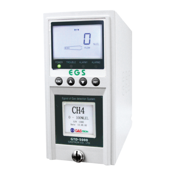
GTD-5000
Instruction Manual
Headquarters / Engineering research laboratory :
23 Gunpo Advance d Industry 1-ro(Bugok-dong), Gunpo-si, Gyeonggi-do
Tel +82-31-490-0800 Fax +82-31-490-0801
Yeongnam business office / Plant :
55 Gonghangap-gil 85beon-gil, Gangseogu, Busan Metropolitan City
Tel +51-973-8518 Fax +51-973-8519
E-mail : info@gastron.com
www.gastron.com
Read in detail for correct use.
Advertisement
Table of Contents

Subscribe to Our Youtube Channel
Related Manuals for GASTRON GTD-5000


Summary of Contents for GASTRON GTD-5000
- Page 1 Headquarters / Engineering research laboratory : 23 Gunpo Advance d Industry 1-ro(Bugok-dong), Gunpo-si, Gyeonggi-do Tel +82-31-490-0800 Fax +82-31-490-0801 Yeongnam business office / Plant : 55 Gonghangap-gil 85beon-gil, Gangseogu, Busan Metropolitan City Tel +51-973-8518 Fax +51-973-8519 E-mail : info@gastron.com www.gastron.com Read in detail for correct use.
- Page 2 Gas detectors satisfying customers. From now on, solve all anguishes concerning Gas detector with the products of Gastron Co. Ltd, We Gastron Co. will take a responsibility and give you satisfaction. In the present instruction manual, operation method for Gas detector as well as simple methods for maintenance and repair, etc.
-
Page 3: Table Of Contents
· · · · · · · · · · · · · · · · · · · · · · · · · · · · · · · · · · · · · · · · · · · · · · · · · · · · 10.1. GTD-5000 Standard Type ·... -
Page 4: Overview
Flow Rate 100 ~ 1,000 ml (Normal 300~500ml / min) GTD-5000 case is made of steel. This product can be installed in areas with leak hazards of all toxic and flammable gases. Gas Sample Line Within 30 m ( 1/4" Tube ) 4-Digit LCD built in the gas detector displays gas leak status at installed site. -
Page 5: Electrical Specifications (Standard Type)
GTD-5000 3. Specification 3. Specification www.gastron.com Instruction Manual 08_09 3.3. Electrical Specifications (Standard Type) 3.4. Environmental Specifications ITEMS SPECIFICATION ITEMS SPECIFICATION Input Voltage(Standard) Absolute min: Transmitter -20 to 60 ℃ Operation Temperature ※ Customer supplied PSU must meet Nominal: Sensor... -
Page 6: Name And Description Of Each Part
Mount holes Holes that fix gas detector to wall or other areas. PoE Connector It is RJ45 Ethernet connector for PoE (Power Over Ethernet) network. [Table 1. GTD-5000 Component Description] NAME DESCRIPTIONS Case cover Protects PCB Board built in Sensor and Housing from external environmental change and shock. -
Page 7: Front Display Configuration
Alarm Setting Icon Displayed when alarm output is forbidden. Fault Icon Displayed when fault is detected during gas detector self-test. [Figure 4. GTD-5000 Assembly Drawing] Alarm2 Icon Displayed during alarm setting or when an alarm is detected. Alarm1 Icon Displayed during alarm setting or when an alarm is detected. -
Page 8: Terminal Pcb Configuration
GTD-5000 5. Installation 5. Installation www.gastron.com Instruction Manual 14_15 5.2. Terminal PCB Configuration 5.3.2. Power and 4~ 20mA Source Configuration ■ Connect 4-20 mA signal terminal at PLC side to 'mA' Type Description of GTD -5000. GND terminal is used in common with RJ45 Ethernet Connector(PoE) power. -
Page 9: Alarm And Rs485 Signal Configuration
Trouble relay output terminal Note1) Use cable designated for RS-485 TRB-COM Trouble relay common terminal Note 2) When there is no RS485 option available for GTD-5000, the following function does not run. AL1-OUT Alarm1 relay output terminal AL1-COM Alarm1 relay common terminal... -
Page 10: Pyrolyzer Configuration
Use J6 Jumper 2-3Pin(PoE), J7 Jumper 1-2Pin(PoE) ·IMAX : Max. Current of GTD -5000 * DC 24 V is supplied for pyrolyzer power through J2 connector of GTD-5000 Terminal Board. ·WIRER/m: The resistance of the wire (ohms/meter value available in wire manufacturer's specification data sheet) ■... -
Page 11: Operation
GTD-5000 6. Operation 6. Operation www.gastron.com Instruction Manual 20_21 6.1. Power On 6.2. Measuring Mode ■ Check connection of operation power (+24V, GND) for CN1 of terminal PCB and 2-3 of J7 Jumper. - It displays gas concentration received from sensor cartridge on LCD digital display in numbers and the ■... -
Page 12: Internal Mode Configuration
GTD-5000 7. System Mode 7. System Mode www.gastron.com Instruction Manual 22_23 7.1. Mode Configuration LEVEL1 LEVEL2 LEVEL3 DEFAULT ZERO no, YES ■ This device consists of the following menu configuration. Current Zero Measurement TYPE Menu Display Description Notes WAIt(Wait) CONFIGURATION MODE... -
Page 13: Configuration Mode
GTD-5000 7. System Mode 7. System Mode www.gastron.com Instruction Manual 24_25 7.3. Configuration Mode - It can be set in between 1%~20% of the full range and default is set at 07 (7%). - When a desired % is displayed, press "FUNC" KEY to set it and enter the next item. -
Page 14: Setting
GTD-5000 7. System Mode 7. System Mode www.gastron.com Instruction Manual 26_27 7.4. Program Setting 7.5. Zero Calibration - When "FUNC" key is pressed for 2 sec or longer in gas concentration display mode at the same time, it - When "FUNC" key is pressed for 2 sec or longer in gas concentration display mode at the same time, it enters menu selection mode. -
Page 15: Span Calibration
GTD-5000 7. System Mode 7. System Mode www.gastron.com Instruction Manual 28_29 7.6. Span Calibration 7.7. Alarm Data Setting (Alarm Mode) - When "FUNC" key is pressed for 2 sec or longer in gas concentration display mode at the same time, - When "FUNC"... - Page 16 GTD-5000 7. System Mode 7. System Mode www.gastron.com Instruction Manual 30_31 - It is a mode that sets Alarm1 Level threshold. It can be set in a range of 1~90% of set high scale value. - Pressing "▲"key or "▼"key increases of decreases Alarm1 threshold, respectively.
-
Page 17: Troubleshooting
GTD-5000 7. System Mode 8. Troubleshooting www.gastron.com Instruction Manual 32_33 8.1. Fault List - Alarm2 (Relay) contact output setting mode message displays "A2rl". FAULT DESCRIPTION & CONDITION CAUSE When a sensor cartridge is not equipped in the main body 1) Sensor cartridge connection fault E-10 - It is a mode that sets alarm2 contact output. -
Page 18: Recovery List
GTD-5000 8. Troubleshooting 9. Interface Configuration www.gastron.com Instruction Manual 34_35 8.3. Recovery List 9.1. MODBUS RS485 9.1.1. Interface setting CAUSE SOLUTION 1) Check status of sensor cartridge connector Sensor cartridge connection fault ■ Data Format: RTU ■ Stop bit: 1bits 2) Change sensor cartridge ■... -
Page 19: Modbus/Tcp Interface
GTD-5000 9. Interface Configuration 9. Interface Configuration www.gastron.com Instruction Manual 36_37 9.2. MODBUS/TCP Interface TYPE ADDRESS BITS DESCRIPTION Decimal point indicator(0~3) 9.2.1. Interface setting 0: 0 Point ■ MMODBUS Port Number 502 1: 1 Point BIT0~2 ■ For details, please go to www. modbus.org... -
Page 20: Drawings And Dimensions
GTD-5000 9. Interface Configuration 10. Drawings and Dimensions www.gastron.com Instruction Manual 38_39 10.1. GTD-5000 Standard Type 구분 ADDRESS BITS DESCRIPTION 40020 BIT0~15 High Scale Value in floating point format word 1 of 2 Real type high scale setting 40021 BIT0~15... -
Page 21: Gtd-5000 & Py-1000
GTD-5000 10. Drawings and Dimensions 10. Drawings and Dimensions www.gastron.com Instruction Manual 40_41 10.2. GTD-5000 & PY-1000 10.3. GTD-5000 & PY-2000 [Figure 15. GTD-5000 and PY-1000] [Figure 16. GTD-5000 and PY-2000]... -
Page 22: Precautions Before Installation
GTD-5000 11. Precautions before Installation 11. Precautions before Installation www.gastron.com Instruction Manual 42_43 11.1. Selecting a Place for Installation (Occupational Health & Safety Act Data) ■ Install in areas where maintenance is convenient. Regular maintenance and correction is required for gas detector. -
Page 23: Revision History
GTD-5000 12. Revision History www.gastron.com Instruction Manual 44_45 Version Contents Date Rev0.0 Initial Revision of Manual 2012.05.31 Rev1.0 * Added alarm write address among MODBUS TCP Address (40001, 40002) 2013.05.02 1. United relay contact method to SPDT (7 Page, 44 Page) Rev2.0...
Need help?
Do you have a question about the GTD-5000 and is the answer not in the manual?
Questions and answers