Advertisement
Build documentation for:
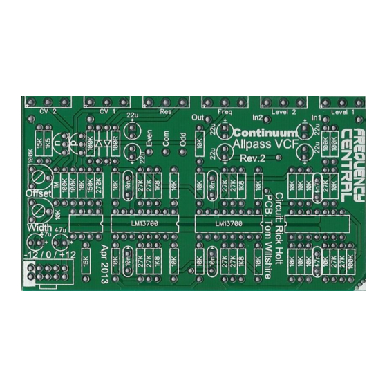
continuum phase shifter
An original design by
Frequency central
Rev 2 / April 2013
B100K
B100K
A100K
B100K
A100K
A100K
Key to PCB screen print:
n: This signifies NPN BC547 transistors. Note the correct pinout as shown by the half circles.
p: This signifies PNP BC557 transistors. Note the correct pinout as shown by the half circles.
Odd: Connects to Odd/Even SPDT lug 1.
Com: Connects to Odd/Even SDPT lug 2.
Even: Connects to Odd/Even SDPT lug 3.
Gnd: Ground
Advertisement
Table of Contents

Related Manuals for Frequency Central Continuum Phase Shifter


Summary of Contents for Frequency Central Continuum Phase Shifter
- Page 1 Build documentation for: continuum phase shifter An original design by Frequency central Rev 2 / April 2013 B100K B100K A100K B100K A100K A100K Key to PCB screen print: n: This signifies NPN BC547 transistors. Note the correct pinout as shown by the half circles.
- Page 2 The screen print is missing the signifier for the single opamp on the left, this is a LF351. The screen print is missing the signifier for the quad opamp on the right, this is a TL084. Please observe that the TL084 is ‘the other way round’ with respect to the LF351 and 2 x LM13700.
- Page 3 Underside of the PCB showing: Ground bus between sockets and PCB Connections between inputs/output and PCB Connections between SDPT and PCB I use solid core for all of the above. RDH 16 May 2013 http://www.frequencycentral.co.uk/...
Need help?
Do you have a question about the Continuum Phase Shifter and is the answer not in the manual?
Questions and answers