Advertisement
Frequency central
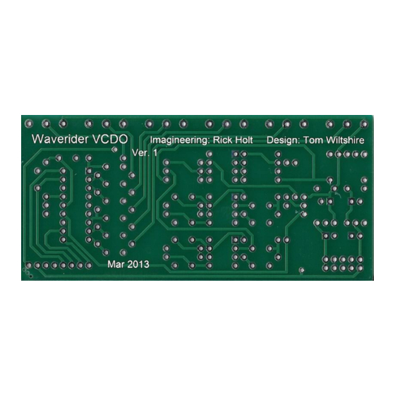
Waverider digital vco
http://www.electricdruid.net/datasheets/VCDO1Datasheet.pdf
Ground (Gnd), Sub (output), >>>
Main (output), +5V, Glide (in).
B100K
B100K
Three fat access holes for calibrating the >>>
trimmers 'from behind' with a jeweller's
screwdriver.
Build documentation for:
Based on the Electric Druid PIC 16F1847 VCDO1:
B10K
B100K
B100K
8 way ribbon
B10K
B10K
<<< Sub, Wave, FM and 1V/oct CV input pads,
Ground pad (Gnd).
B10K
B10K
8 way ribbon
B10K
Advertisement
Table of Contents

Subscribe to Our Youtube Channel
Related Manuals for Frequency Central Waverider Digital VCO


Summary of Contents for Frequency Central Waverider Digital VCO
- Page 1 Frequency central Build documentation for: Waverider digital vco Based on the Electric Druid PIC 16F1847 VCDO1: http://www.electricdruid.net/datasheets/VCDO1Datasheet.pdf B10K B10K B10K B10K B10K B10K Ground (Gnd), Sub (output), >>> Main (output), +5V, Glide (in). 8 way ribbon B100K B100K B100K B100K <<<...
- Page 2 Things to note on the photo below: 8 way ribbon between the two PCBs Ground bus connecting all sockets and terminating in the CV PCB Gnd pad. CV inputs x 4, solid core to CV PCB pads. Glide LED, the 1K CLR (inside the black heatshrink) connects between the LED anode and the Glide input, the LED cathode connects to the ground bus.
- Page 3 Glide status LED Glide is ‘always on’ providing there is no jack in the Glide input socket as the normalise lug of the socket receives +5V from connection to the Main PCB, the glide amount being determined by the Glide knob. Inserting a jack into the Glide input socket disables ‘always on’, and Glide will only occur when the Glide input socket receives a +5V gate signal.
Need help?
Do you have a question about the Waverider Digital VCO and is the answer not in the manual?
Questions and answers