Advertisement
Table of Contents
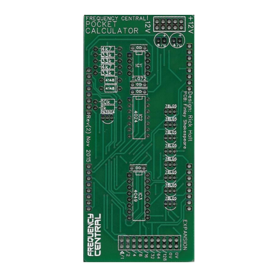
Frequency central
Pocket calculator
1K x 20
4K7 x 2
10K x 1
33K x 5
100K x 2
All resistors are ¼ watt
metal film
* or BC547, but rotate by 180° for different pinout.
** yes 8 x 78L05. One is used as a 5V regulator, the other seven are used as output buffers.
*** you can use either type of switch, pads are provided for both. I prefer the Tactile type.
Build documentation for:
rev(2)
Bill of Materials
10nF x 2
100nF x 4
47uF x 2
CD4024 x 1
CD4049 x 1
TL072 x 1
2n3904 x
1*
1n4148 x 3
78L05 x
8**
3mm green LED x 7
Power header
Male header strip
Female header strip
Kobiconn sockets x 16
Momentary switch***:
Tactile
or
Push button
Advertisement
Table of Contents

Related Manuals for Frequency Central Pocket Calculator Rev(2)


Summary of Contents for Frequency Central Pocket Calculator Rev(2)
- Page 1 Frequency central Build documentation for: Pocket calculator rev(2) Main PCB Panel PCB Bill of Materials 1K x 20 10nF x 2 CD4024 x 1 Power header 4K7 x 2 100nF x 4 CD4049 x 1 Male header strip 10K x 1...
- Page 2 Main PCB Populate the Main PCB as shown on the silkscreen, starting with the lowest profile components, so: Resistors IC sockets Non-electrolytic capacitors, transistor, voltage regulators Power header and expansion header Electrolytic capacitors Finally, cut 4 male header strips to the correct lengths and solder to the PCB so that the long legs stick out of the rear of the PCB.
- Page 3 Panel PCB Populate the Panel PCB as shown on the silkscreen in this order: Resistors and diode Capacitors Switch*: the four pads are sized so that the switch sits on them rather than going through them. Solder from the component side rather than flipping it over to solder. This ensures the switch fits snug to the PCB, and that it’s head protrudes through the panel by the correct amount.
- Page 4 Push the 7 LEDs through their holes, remembering that the long legs go through the holes marked ‘+’. Don’t solder them in place yet! Mount the panel PCB onto the panel, tighten up all the nuts – it’s worth checking that the LEDs will fit smoothly through the holes before doing this, as some can be a little tight –...
Need help?
Do you have a question about the Pocket Calculator Rev(2) and is the answer not in the manual?
Questions and answers