Advertisement
Frequency central
Build documentation for:
Meth amp Rev.2
Meth Amp is based around the fuzz core of the EH Big Muff pedal. The clipping diodes have
been replaced by red LEDs to take account of the change in power supply from 9V in the
original Big Muff to +/-12V in Meth Amp. To the fuzz core has been added a bunch of OTAs,
each controlling a different aspect of audio processing: gain, regen (a new feature – not
present in Big Muff), tone and volume. Thereby, each feature is fully voltage controllable.
Additionally, there is a separate x100 preamp which can be used to boost external audio for
further processing by Meth Amp.
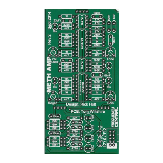
Main PCB:
Panel PCB:
Please observe correct polarity of the electrolytic caps (indicated by +), transistors, ICs (pin 1
indicated by square pad), LEDs (cathode indicated by flat edge) etc!
'n' = npn transistor BC547
'p' = pnp transistor BC557
Advertisement
Table of Contents

Related Manuals for Frequency Central Meth Amp Rev.2


Summary of Contents for Frequency Central Meth Amp Rev.2
- Page 1 Frequency central Build documentation for: Meth amp Rev.2 Meth Amp is based around the fuzz core of the EH Big Muff pedal. The clipping diodes have been replaced by red LEDs to take account of the change in power supply from 9V in the original Big Muff to +/-12V in Meth Amp.
- Page 2 Bill of Materials 100R x 8 33pF x 1 LM13700 x 2 B100K x 8 All pots are 9mm Alpha 1K x 4 150pF x 1 TL072 x 2 2K2 x 4 330pF x 1 TL084 x 1 100K trimmer x 4 4K7 x 4 470pF x 2 BC547 x 2...
- Page 3 Main PCB: Populate the Main PCB as shown on the silkscreen, starting with the lowest profile components, so: Resistors IC sockets Non-electrolytic capacitors, transistors, trimmers Power header Electrolytic capacitors Finally, cut 3 male header strips to the correct lengths (4, 4, 4) and solder to the PCB so that the long legs stick out of the rear of the PCB.
Need help?
Do you have a question about the Meth Amp Rev.2 and is the answer not in the manual?
Questions and answers