Advertisement
Quick Links
Frequency central
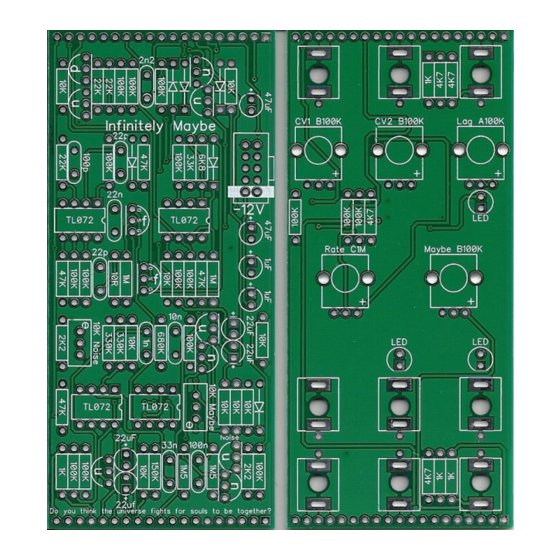
Infinitely Maybe
Infinitely Maybe is a full featured randomness module, with a number of sources of
randomness:
• White noise
• Pink noise
• Sample and hold circuit
• Random gates circuit
An onboard CV mixer allows you to mix two different sources into the sample and hold
circuit. White noise is normalised to CV input 1, Pink noise is normalised to CV input 2
Infinitely Maybe has an onboard clock for triggering the sample and hold circuit. This may be
overridden with an external clock if required via the clock in socket.
There is a built in LAG circuit, which enables the S/H OUT to slide between voltages at a
predetermined rate. This function can be remotely controlled via the LAG IN
Finally, a random gates output is derived from the S/H Out. With the MAYBE knob at 0 a
constant gate is available. The further you turn the MAYBE knob towards 10, the less
likelihood of a gate is.
Build documentation for:
Main PCB
Pots 'n' sockets PCB
Advertisement

Subscribe to Our Youtube Channel
Related Manuals for Frequency Central Infinitely Maybe


Summary of Contents for Frequency Central Infinitely Maybe
- Page 1 White noise is normalised to CV input 1, Pink noise is normalised to CV input 2 Infinitely Maybe has an onboard clock for triggering the sample and hold circuit. This may be overridden with an external clock if required via the clock in socket.
- Page 2 Key to PCB screen print: n: This signifies NPN BC547 transistors. Note the correct pinout as shown by the half circles. p: This signifies PNP BC557 transistors. Note the correct pinout as shown by the half circles. f: This signifies 2N5485 FETs. Note the correct pinout as shown by the half circles. The PCB shows the correct orientation for BC547/BC557/2N5485.
- Page 3 Main PCB assembly 1. Firstly, there’s a little hack to do to eliminate the need for the Maybe trimmer. Insert diode as shown above, bend it’s leg around to the trimmer’s middle pad as shown. 2. Solder all resistors and the rest of the diodes 3.
- Page 4 Note: Not all pots and sockets are equal in height. Providing you use the ones in the links provided, everything will line up perfectly. Make sure that you plug the Main PCB into the Pots ‘n’ sockets PCB the right way around – Infinitely Maybe logo should be the right way up.
- Page 5 Calibration 10K Noise: Turn both CV inputs to maximum, this sends white and pink noise to the sample and hold circuit. Turn the slew knob to minimum. Plug the SH Out into a filter set to self oscillate, or a VCO, so you can monitor the random voltages the SH Out gives out. Adjust the noise trimmer so the noise level is as loud as it can be without causing the S/H output to slew.
Need help?
Do you have a question about the Infinitely Maybe and is the answer not in the manual?
Questions and answers