
Related Manuals for Korenix JetCon 2302


Summary of Contents for Korenix JetCon 2302
- Page 1 JetCon 2302 Industrial 2-Channel Fast Ethernet to Fiber Media Converter User’s Manual Version: 1.0 Date:26-Aug,2010...
- Page 2 JetCon 2302 Industrial 2-Channel Media Converter Copyright Notice Copyright © 2010 Korenix Technology Co., Ltd. All rights reserved. Reproduction in any form or by any means without permission is prohibited.
- Page 3 Declaration of CE This product has passed the CE certification for environmental specifications. Test conditions for passing included the equipment being operated within an industrial enclosure. In order to protect the product from being damaged by ESD (Electrostatic Discharge) and EMI leakage, we strongly recommend the use of CE-compliant industrial enclosure products.
-
Page 4: Table Of Contents
Content 1. Introduction ..........1 1-1. Features ............... 2 1-2. Packing checklist..........3 2. Hardware Description ........4 2-1. Dimensions............4 2-2. Front Panel............5 2-3. Bottom View ............6 2-4. Wiring System Power Inputs ........ 7 2-5 Connecting the Alarm Relay Output...... 8 2-6. -
Page 5: Introduction
JetCon 2302 User’s Manual 1. Introduction JetCon 2302 is not only a compact 4-port switch, but also a 2 channel RJ45 to fiber media converter - an ideal model that would physically fit in harsh environments with intensive severe electromagnetic interference. In switch mode, JetCon 2302 is an Industrial 4-port 10/100Mbps Fast Ethernet Fiber Switch, incorporating 3.2Gbps switching fabric with... -
Page 6: Features
In field site applications, unstable power input always impacts on the reliability of system and causes an interruption of communication. To provide a higher reliability, JetCon 2302 has a wide range redundant power input 10~60VDC that meets the NEMA-TS2 requirements for power variation. -
Page 7: Packing Checklist
1-2. Packing checklist JetCon 2302 includes following items: 1 set of JetCon 2302 with DIN Rail Clip Quick Installation Guide x1 JetCon 2302 Quick Installation Guide To get more information about operating instructions, please visit http://www.korenix.com/downloads.htm for user’s manual download. -
Page 8: Hardware Description
2-5. Wiring the Alarm Event Relay Output 2-6. System LED indicators 2-7. Connecting the Ethernet Port 2-1. Dimensions The dimensions of JetCon 2302 are 120 mm (H) x 55 mm (W) x 108 mm (D). Detailed mechanical design drawings are illustrated below:... -
Page 9: Front Panel
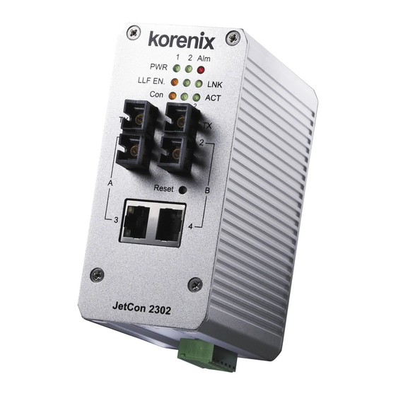
2-2. Front Panel The Front Panel of the JetCon 2302 is shown in Figure A as below. Alarm Relay Indicator Power Indicators Fiber Port Indicators Converter Mode Indicator Channel B Fiber port A Channel at Converter Mode B Channel at... -
Page 10: Bottom View
2-3. Bottom View The bottom side of JetCon 2302 is shown in the below Figure B. It includes one 7-pin DIP switch for system configuration and one 6-pin removable terminal block for the redundant power inputs and event alarm relay output. -
Page 11: Wiring System Power Inputs
2-4. Wiring System Power Inputs The JetCon 2302 supports DC 10~60V wide range redundant power input and also supports negative power system for telecom applications. The following diagrams show the wiring architectures of positive and negative power systems. 1. Insert the power wires into the V+ and V- contacts of the terminal block connector respectively. -
Page 12: Connecting The Alarm Relay Output
2-5 Connecting the Alarm Relay Output JetCon 2302 supports one dry alarm relay output for power and port event to alert administrator. The specification of relay conductor is 24W when it connects with a DC 24V power source. The maximum current is 1A. Following diagram shows how to make an alarm circuit. -
Page 13: System Led Indicators
2-6. System LED Indicators The front panel of JetCon 2302 includes 2 Power LEDs, 1 LED for alarm relay active indication, 1 LED for operating mode indication, 2 LEDs per each Fiber port for link and activity indication. The following table describes the functions for each LED indicator. -
Page 14: Connecting The Ethernet Ports
2-7. Connecting the Ethernet ports The JetCon 2302 supports 2 10/100TX RJ-45 ports and 2 100Base-FX fiber ports. The wiring methods for the RJ-45 and fiber ports are described in this session. They also include the specifications of fiber port. - Page 15 Specification of Fiber port The fiber port is provided in the JetCon 2302 only with different link distances shown on the label that sticks on the rear side. To get a good transmission quality, the attenuation of fiber cable should be noticed and be considered when executing system design.
-
Page 16: Din Rail Mounting
JetCon device onto the standard DIN Rail. Follow the steps below to mount the JetCon 2302 on the DIN-Rail track. 1. Insert the upper end of the DIN-Rail clip into the back of the DIN-Rail track from its upper side. -
Page 17: System Configuration
4. System Configuration All of the JetCon 2302 features are configured by a 7-pin DIP Switch, after changing the settings, JetCon 2302 should execute resetting procedure. The following table describes the function of each DIP switch: DIP switch Status Description Port link down event alarm enabled. - Page 18 makes the device a cost effective solution eliminating the need of multiple fiber network installations. The exact operating behaviors of Switch mode and Converter mode are shown in the following descriptions and figures. Switch Mode – the device works as a switch, which is equipped with 2 10/100TX RJ-45 ports and 2 100Mbps fiber ports.
- Page 19 Note: It is necessary to execute system reset or power reset when changing the operating mode; otherwise the new operating setting will not apply.
-
Page 20: System Installation
5. System Installation Following figure illustrates a typical application of JetCon 2302 in Switch mode and Converter mode: application diagram, JetCon 2302 provides graceful anti-electromagnetic interference that ensures the reliable communication not interfered by the noises generated from the motors of facility, railway/subway power system or Intelligent Traffic Control System. -
Page 21: Installation And Testing
IP address and supports ICMP protocol. 9. Make sure the JetCon 2302 is working at switch mode. If it doesn’t, set the DIP switch to off and reset the JetCon 2302. 10. Execute “Ping 192.168.1.1 –t” from the desktop pc command line mode and make sure these are echo packets from target device. - Page 22 11. Change the mode to converter mode and connect both fiber ports using proper fiber cable, then test the fiber port by sending the ICMP packet process as the procedure-10. The figure of testing architecture is as follows. [Note] Make sure that the connected network switches support MDI/MDI-X function. If they do not support this function, use a crossover Ethernet cable.
- Page 23 Type ping 192.168.1.1 command to check the connection. Here we use IP address 192.168.1.1 as an example. Repeat step 10 to make sure that the connection of each device linked to the JetCon Converter is successfully established. Power on the PC host, activate the Command Line mode, and ping the connected Ethernet device by typing “ping 192.168.1.1 –t”...
- Page 24 Before you continue, make sure that both PWR1 and PWR2 are successfully connected to power sources. When PWR1 fails, the LED for PWR1 will go out. At that moment, if the ping command is still being replied to, then it proves that the redundant power input function works normally.
-
Page 25: Troubleshooting
6. Troubleshooting Make sure you are using the correct DC power supplies and that the voltage measured at the power connector is DC10 to 60 V. Do not use power supplies with DC output over 60V. It may damage the device. Select Ethernet cable with specifications suitable for your applications to set up your systems. - Page 26 2 × 100Mbps Fiber port, SC or ST (optioned). Fiber port JetCon 2302-m: Multi-mode (Channel A,B) JetCon 2302-s : Single-mode (Channel A,B) JetCon 2302-ms : Multi-mode (Channel A), Single-mode (Channel B) (Please contact with sales ) Ethernet Copper RJ-45 Ethernet port : 100 Meters...
- Page 27 DIP Switch 6: Power Event Alarm Control, Enable(On)/ Disable (Off) DIP Switch 7: Not available. Power Connector 6-pin Removable Terminal Block Digital Output Included in 6-pin Removable Terminal Block Power Requirements System power DC 10~60V with polarity reverses correction. Supports Positive/Negative power system System power 6Watts / DC 24V consumption...
- Page 28 Revision History Edition Date Modifications 23-July,2010 New edition 26-Aug,2010 Remove LLF function, modify all drawing. V1.0 30-Aug, 2010...
- Page 29 Less Time At Work! Fewer Budget on applications! The Korenix business idea is to let you spend less time at work and fewer budget on your applications. Do you really want to go through all the troubles but still end up with low quality products and lousy services? Definitely not! This is why you need Korenix.
Need help?
Do you have a question about the JetCon 2302 and is the answer not in the manual?
Questions and answers