
Related Manuals for Korenix JetCon 2301S


Summary of Contents for Korenix JetCon 2301S
- Page 1 JetCon 2301S Industrial Fast Ethernet to Fiber Rail Media Converter User’s Manual Version 1.1 Apr., 2018...
- Page 2 Copyright Copyright © 2014 all rights reserved. No part of this publication may be reproduced, adapted, stored in a retrieval system, translated into any language, or transmitted in any form or by any means without the written permission of the supplier. About This Manual This user manual is intended to guide professional installer to install the JetCon 2301S and how to build the infrastructure centered on it.
- Page 3 Declaration of CE This product has passed the CE certification for environmental specifications. Test conditions for passing included the equipment being operated within an industrial enclosure. In order to protect the product from being damaged by ESD (Electrostatic Discharge) and EMI leakage, we strongly recommend the use of CE-compliant industrial enclosure products.
-
Page 4: Table Of Contents
1. Introduction ....................... 5 1-1. Features ......................6 1-2. Package Checklist .................... 6 2. Hardware Description and Installation ..............7 2-1. Dimensions ..................... 7 2-2. Front Panel Information .................. 8 2-3. Bottom View ....................8 2-4. Wiring the DC power input ................9 2-5. -
Page 5: Introduction
JetCon 2301S. Multi-Forwarding Modes The JetCon 2301S supports 4 types of forwarding modes - Store and Forward, Modify Cut-through, Pure Converter and Converter with Auto-change mode for fulfilling extreme low latency requirements – Fieldbus and EtherCAT, with invariant forwarding latency in 64~1600 bytes packet length. -
Page 6: Features
1-2. Package Checklist JetCon 2301S includes the following items: JetCon 2301S with DIN Rail Clip Quick Installation Guide Quick Installation Guide JetCon 2301S To get more information about the JetCon 2301S, please visit http://www.korenix.com/downloads.htm for user’s manual download. -
Page 7: Hardware Description And Installation
2. Hardware Description and Installation This session introduces JetCon 2301S enclosure port information, panel design and describes how to install the system with other equipments. 2-1. Dimensions The dimensions of JetCon 2301S are as below: 120mm (H) x 30mm (W) x 99mm (D) (without DIN Rail Clip) -
Page 8: Front Panel Information
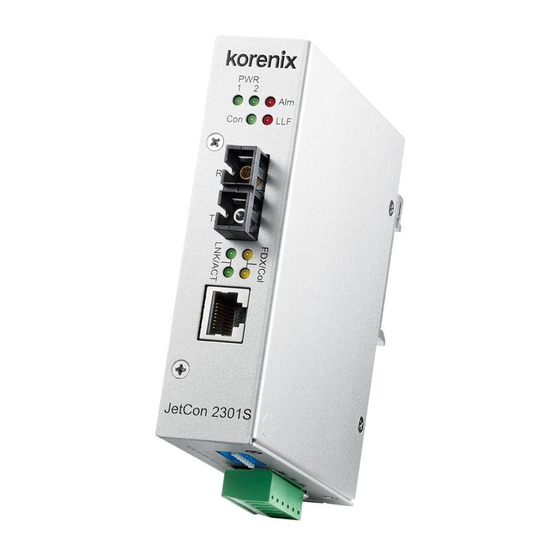
2-2. Front Panel Information The Front Panel of JetCon 2301S is shown figure–A as below. It includes 1 Fast Ethernet Copper (RJ-45 connector) port, 1 100Base-FX Fiber port (SC or ST type connector) and 9 diagnostic LEDs. 2-3. Bottom View... -
Page 9: Wiring The Dc Power Input
2-4. Wiring the DC power input The JetCon 2301S supports 2 power inputs with power redundancy and wide range input 10V~ 60V DC. The following diagram shows the wiring architecture. 1. Insert the positive and negative wires into the V+ and V- contacts of the terminal block connector respectively. -
Page 10: Connecting The Dry Relay Output
2-5. Connecting the Dry Relay Output JetCon 2301S supports one alarm relay output for power and port event to alert administrator. The specification of relay conductor is 24W when it connects with a DC 24V power source, and maximum current is 1A. The following diagram shows how to make an alarm circuit. -
Page 11: Connecting The Ethernet Port
10/100Mbps. The following diagram shows the straight through cable and cross-over cablings. The RJ-45 ports of JetCon 2301S support auto-MDI/MDI-X function without any cable change when you use an Ethernet cable to connect other devices, such as computers, switches or hubs. - Page 12 RX port. Specification of Fiber port The JetCon 2301S fiber port supports different fiber link distances, as the resulting the quality of optical fiber cable is quit important. Most of users are confused about the relation of fiber transceiver and optical fiber cable. The following table will show you the specifications of fiber transceiver installed in JetCon 2301S.
-
Page 13: Din Rail Mounting
3. DIN Rail Mounting The DIN Rail clip is screwed on the rear panel of JetCon 2301S, which supports EN 50022 type rail installation. The following diagram includes the dimension of EN50022 rail for your reference. The DIN Rail should be behind the spring when installing the JetCon 2301S onto the DIN Rail. -
Page 14: System Configuration
These forwarding modes are configured by DIP switch allocated at bottom side. Besides, to provide real time alert, the JetCon 2301S adopts Link Loss Forwarding mechanism that follows TS-1000 standard and enables an alarm relay output to inform system engineer or trigger another alarm system. -
Page 15: Forwarding Mode
Note: After changing the DIP Switch, please reset power to activate the function. 4-3. Link Loss Forwarding (LLF) function The JetCon 2301S provides Link Loss Forwarding feature. When the LLF feature is enabled, the TP port link status will be informed to the Fiber port of same device and vice versa. -
Page 16: Event Alarm Configuration
1. Take out your JetCon 2301S Industrial Fast Ethernet Media Converter from the package box. 2. Check if the DIN-Rail clip is attached to the JetCon 2301S. If the DIN-Rail clip is not attached to the JetCon 2301S, refer to DIN-Rail Mounting section for... - Page 17 3. To place the JetCon 2301S on the DIN-Rail track or wall, refer to the Mounting Installation section. 4. Pull the terminal blocks off the JetCon 2301S and wire the power lines. Refer to the Wiring the DC Power Inputs section for how to wire the power inputs.
- Page 18 13. Repeat step 10 to make sure that the connection of each device connected to the JetCon 2301S is successfully established. 14. Power on the host, activate the Command Line mode, and ping the connected Ethernet device by typing “ping 192.168.1.1 -t”...
- Page 19 At that moment, if the ping command is still replying, then it proves that redundant power input function works normally. 17. Exit the Command Line mode, and connect PWR1 power input. At this stage, your JetCon 2301S has been tested and the installation is completed.
-
Page 20: Trouble Shooting
6. Trouble shooting Make sure you are using the correct DC power suppliers (DC12~ 48 V) or power adapters. Select Ethernet cables with specifications suitable for your applications to set up your systems. Ethernet cables are categorized into unshielded twisted-pair (UTP) and shielded twisted-pair (STP) cables. -
Page 21: Product Specifications
Interface Ethernet copper port 1 10/100TX ports with Auto MDI/MDI-X, Auto Negotiation. Fiber port 1 100Mbps Fiber port, SC or ST (optioned). JetCon 2301S-m/JetCon 2301S-mw: 2KM (Max.) Wave-length: 1310nm Min TX Power:-19dBm Max TX Power:-14dBm Min RX Sensitivity:-14dBm Max RX Sensitivity:-31dBm Link budget:12dB JetCon 2301S-s/JetCon 2301S-sw: 30KM (Max.) - Page 22 RJ-45 Ethernet port : 100 Meters Ethernet Copper Cable 10Base-T: 2-pairs UTP/STP Cat-3,4 TIA/EIA 568-B cable 100Base-TX : 2/4 pairs UTP/STP Cat.5 TIA/EIA 568-B cable Ethernet Fiber Cable JetCon 2301S-m: 2KM distance, 50~62.5/125um Multi-mode fiber Cabel. JetCon 2301S-s: 30KM distance,8~10/125um Single-mode fiber cable. Diagnostic LEDs...
- Page 23 Alarm Relay Output Included in 6-Pin Removal Terminal Block Power Requirements System power Redundant Power DC 10~60V with polarity reverse correction. Supports Positive/Negative power system System power 5 Watts / DC 24V consumption Mechanical System Installation DIN Rail / Wall mount installation Enclosure protection Ingress Protection code –...
- Page 24 Revision History: Edition Date Modifications V1.0 7-Aug-2017 Release version. V1.1 19-Apr-2018 Update the operating temp. from 70°C to 75°C...
Need help?
Do you have a question about the JetCon 2301S and is the answer not in the manual?
Questions and answers