Table of Contents
Advertisement
Quick Links
Advertisement
Table of Contents

Related Manuals for DMP Electronics ITI 738I


Summary of Contents for DMP Electronics ITI 738I
- Page 1 738I ITI™ Interface Module INSTALLATION AND PROGRAMMING GUIDE...
-
Page 3: Table Of Contents
TABLE OF CONTENTS About the 738I ITI™ ........1 Product Specifications ......15 Supported Wireless Receivers Certifications ..........16 and Transmitters ..........2 Install the 738I ITI™ ........4 Mount the Module ..........4 Wire the Module ..........6 Program the 738I ITI™ ........8 Initialization ............ -
Page 5: About The 738I Iti
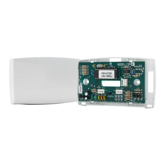
ABOUT THE 738I ITI™ The 738I ITI™ Wireless Interface Module allows you to interface ITI™ SuperBus™ 2000 Series Wireless receivers with the DMP XT30/XT50 Series and XR150/XR550 Series panels. This module allows up to 96 supervised, programmable zones of ITI wireless transmitters when used with the ITI™... -
Page 6: Supported Wireless Receivers And Transmitters
Supported Wireless Receivers and Transmitters The maximum wire distance between the ITI wireless receiver and the 738I is 3 feet. Table 1 lists the wireless receivers supported and Table 2 lists the wireless transmitters supported. NUMBER OF SUPPORTED ZONES MODEL NAME XT30 XT50 XR150/XR550... - Page 7 MODEL NAME ITI MODEL NUMBER MODEL NAME ITI MODEL NUMBER 2-Button SAW Keychain SAW PIR Motion Sensor 60-639-95R 60-707-0195R Touchpad Wireless AP750W PIR 60-880-95 4-Button SAW Keychain 4-Button SAW Keychain Motion Sensor 60-659-95R Touchpad* Touchpad* SAW Pet Immune PIR 60-807-95R Motion Sensor 2-Button Crystal Keyfob 60-607-319.5...
-
Page 8: Install The 738I Iti
INSTALL THE 738I ITI™ Mount the Module Mount on Wall The module comes in a case that mounts directly to walls, backboards, or other flat surfaces. Wire entrances are on the back and each side of the case. Two screw holes at the bottom of the case are for mounting the case on single-gang switch boxes or rings. - Page 9 Figure 1: Standoff and Module Installation Digital Monitoring Products, Inc. 738I ITI™ Installation and Programming Guide...
-
Page 10: Wire The Module
Wire the Module The 738I connects to the panel 4-wire keypad data bus of XT30/XT50 Series panels and panel 4-wire keypad data bus and the LX-Bus™ of XR150/XR550 Series panels. Use a 4-wire harness to easily connect the 738I to an ITI Wireless Receiver. Note: When programming 738I zones on the LX-Bus of an XR150/XR550 Series panel, select NO when prompted whether the zone is wireless. - Page 11 PROG Header When programming the 738I, connect the provided Model 330 programming cable (with two 4-wire connectors) from the PROG header to any DMP thinline, wireless, or graphic touchscreen keypad. PROGRAM Header Place the provided jumper across the PROGRAM header to enter 738I programming mode.
-
Page 12: Program The 738I Iti
PROGRAM THE 738I ITI™ Connect the Model 330 Programming Cable from the PROG header to any DMP thinline, wireless, or graphic touchscreen keypad set to address 1. Refer to the specific keypad installation sheet for information on changing the keypad address. Place the jumper across the PROGRAM header. -
Page 13: Zone Number
Zone Number Enter the two-character zone number (01 - 96) to be ZONE NO: programmed. If the zone number is less than 10, enter a leading zero, such as 01. Refer to Table 3 for Keypad Bus Zone numbers. Press CMD to accept the entry. For LX-Bus Zone Numbers, enter the right two digits of the zone number. - Page 14 LX-BUS ZONE NUMBERS XR150 SERIES XR550 SERIES 738I ZONE LX-BUS LX-BUS LX-BUS LX-BUS LX-BUS LX-BUS Table 4: LX-Bus Zone Numbers 738I ITI™ Installation and Programming Guide Digital Monitoring Products, Inc.
- Page 15 LX-BUS ZONE NUMBERS XR150 SERIES XR550 SERIES 738I ZONE LX-BUS LX-BUS LX-BUS LX-BUS LX-BUS LX-BUS Table 5: LX-Bus Zone Numbers Continued Digital Monitoring Products, Inc. 738I ITI™ Installation and Programming Guide...
-
Page 16: Transmitter Type
Transmitter Type Enter a transmitter type by pressing the Select keys below the type of transmitter used as shown on the LCD. For example, press the third from the left Select key to choose unsupervised. Refer to the installation instructions provided with the ITI transmitter for additional information. -
Page 17: Transmit Now
Transmit Now This is the transmitter learn function and the message TRANSMIT NOW displays until the learn function completes. You must trip the transmitter tamper by removing the cover. This sends a transmitter identification to the 738I, identifying the device. The 738I stores the identification and learns the transmitter. -
Page 18: Exit Programming
Exit Programming Remove the jumper from the PROGRAM header to exit the 738I programming mode. Place the jumper over one pin for future use. Remove the Model 330 cable and the 32-character keypad from PROG header. After exiting programming mode, all zone states report to the panel as NORMAL. -
Page 19: Product Specifications
PRODUCT SPECIFICATIONS Primary Power 12 VDC Current Draw 42 mA Zones 5 VDC, 2 mA max Dimensions 4.5” W x 2.75” H x 1.75” D 11.43 W x 7 H x 4.45 D cm Digital Monitoring Products, Inc. 738I ITI™ Installation and Programming Guide... -
Page 20: Certifications
CERTIFICATIONS FCC Part 15 738I ITI™ Installation and Programming Guide Digital Monitoring Products, Inc. - Page 21 Information furnished is believed to be accurate and reliable. This information is subject to change without notice. Digital Monitoring Products, Inc. 738I ITI™ Installation and Programming Guide...
- Page 22 738I ITI™ Installation and Programming Guide Digital Monitoring Products, Inc.
- Page 24 LT-0415 20161 © 2020 Digital Monitoring Products, Inc.
Need help?
Do you have a question about the ITI 738I and is the answer not in the manual?
Questions and answers